1、PID algorithm control
1、PID algorithm control1.1、Debugging method1.2、PID algorithm theory1.2.1, proportion part1.2.2, integral part1.2.3, differential part1.3、PID algorithm selection1.3.1、Positional PID algorithm1.3.2、Incremental PID algorithm
Note: PID has been debugged before the product leaves the factory. It is not recommended to adjust it by yourself, which may cause problems with subsequent functions. But you can learn debugging methods and operating steps.
Function package path: ~/transbot_ws/src/transbot_bringup
1.1、Debugging method
View code---transbot_driver.py
def dynamic_reconfigure_callback(self, config, level): # self.bot.set_pid_param(config['Kp'], config['Ki'], config['Kd']) ... ... Find the self.bot.set_pid_param() function in the above two functions. The PID is not adjustable by default. If you need to adjust, remove the [#] in front.
In order to facilitate debugging, use the remote control method to debug.
Either jetson nano or a virtual machine can be the master, but the ros Master must be started by the master.
Take jetson nano as the Master as an example.
jetson nano side
xxxxxxxxxxroscorerosrun transbot_bringup transbot_driver.pyvirtual machine
xxxxxxxxxxrqt_plot # rqt visualization toolrosrun rqt_reconfigure rqt_reconfigure # Parameter adjusterrosrun teleop_twist_keyboard teleop_twist_keyboard.py # Keyboard control node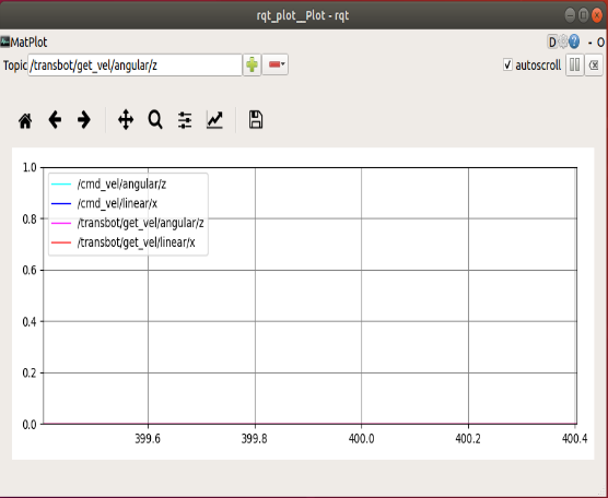
First select the debugging parameters, as shown in the figure. After entering each parameter name, click [+] to add, click [-] to delete.
- /cmd_vel/angular/z :target angular velocity
- /cmd_vel/linear/x : target linear velocity
- /transbot/get_vel/angular/z :current angular velocity
- /transbot/get_vel/linear/x:current linear velocity
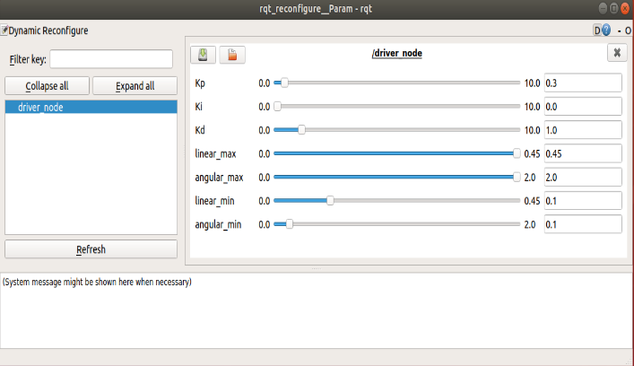
As shown below, select the [driver_node] node. We only need to adjust the three parameters [Kp], [Ki], and [Kd], and do not adjust the others.
Debugging steps:
In the keyboard control terminal, use the keys of the keyboard to drive the car to move [forward], [backward], [turn left], and [turn right]
Observe the [rqt_plot] window image changes, so that the current angular velocity is close to the target angular velocity, and the current linear velocity is close to the target linear velocity. It is impossible to overlap. The target speed is ideal, without any interference, and the speed can be added instantly.
Use the keyboard [q], [z], [w], [x], [e], [c] to increase or decrease the speed to test the status of different speeds.
Observe the changes of [rqt_plot], adjust the data of [Kp], [Ki], and [Kd] through [rqt_reconfigure], test multiple times, and select the best data.
Keyboard control instructions
xxxxxxxxxxanything else : stopq/z : increase/decrease max speeds by 10%w/x : increase/decrease only linear speed by 10%e/c : increase/decrease only angular speed by 10%| Button | Robot car[linear,angular] | Button | Robot car[linear,angular] |
|---|---|---|---|
| 【i】or【I】(advance) | 【 linear,0】 | 【u】 或【U】 | 【linear,angular】 |
| 【,】(back) | 【-linear,0】 | 【o】 或【O】 | 【linear,- angular】 |
| 【j】or【J】(Turn left) | 【0, angular】 | 【m】或【M】 | 【- linear,- angular】 |
| 【l】or【L】(Turn right) | 【0,- angular】 | 【.】 | 【 - linear,angular】 |
After debugging, the PID is automatically stored in the PCB, and the PID setting part can be commented out according to the original way of viewing the source code.
Note: Other gameplay requires PID debugging, the theory is the same, the theory is for reference.
1.2、PID algorithm theory
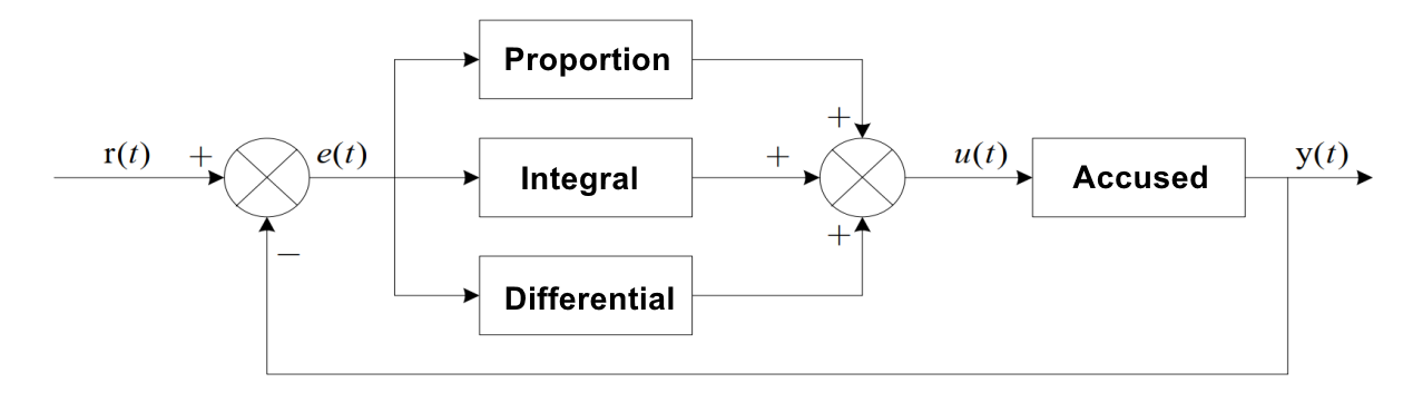
PID is to perform proportional integral derivative calculation on the input deviation, and the superimposed result of the calculation is used to control the actuator. The formula is as follows:
$u(t)=K_p[e(t)+\frac{1}{T_i}\int_{0}^{t}e(t)dt+Td\frac{de(t)}{dt}]$
It consists of three parts:
-P is the ratio, that is, the input deviation is multiplied by a coefficient;
-I is the integral, which is the integral operation of the input deviation;
-D is differential, which performs differential operation on the input deviation.
The following figure shows a basic PID controller:
1.2.1, proportion part
The mathematical expression of the proportional part is: $K_p*e(t)$
1.2.2, integral part
The mathematical expression of the integral part is: $\frac{K_p}{T_i}\int_{0}^{t}e(t)dt$
1.2.3, differential part
The mathematical expression of the differential part is: $K_p*Td\frac{de(t)}{dt}$
1.3、PID algorithm selection
Digital PID control algorithms can be divided into positional PID and incremental PID control algorithms. Then we should first understand its principle before deciding which PID algorithm to use:
1.3.1、Positional PID algorithm
$u(k)=K_pe(k)+K_I\sum_{i=o}e(i)+K_D[e(k)-e(k-1)]$
e(k): The value set by the user (target value)-the current state value of the control object
Proportion P: e(k)
Integral I: the accumulation of ∑e(i) errors
Differential D: e(k)-e(k-1) this time error-last time error
That is to say, the positional PID is the actual position of the current system, and the deviation from the expected position you want to achieve is used for PID control.
1.3.2、Incremental PID algorithm
$\Delta u(k)=u(k)-u(k-1)=K_P[e(k)-e(k-1)]+K_ie(k)+K_D[e(k)-2e(k-1)+e(k-2)]$
Proportion P: $e(k)-e(k-1)$ this time error-last time error
Integral I: $e(k)$ error
Differential D: $e(k)-2e(k-1)+e(k-2)$ This time error-2*Last error+Last last error