6、Data calibration
6、Data calibration6.1、imu calibration6.1.1、Calibration steps6.1.2、Related nodes6.2、Linear speed calibration6.3、Angular velocity calibration
Note: The parameters have been calibrated before the product leaves the factory, and generally do not need to be calibrated.
If you feel that there are large deviation when control car, you need to calibrate [imu], [linear velocity], [angular velocity]; before calibration, please place the robot on a flat ground and do not move the robot.
6.1、imu calibration
The error of IMU mainly comes from three parts, including noise (Bias and Noise), scale factor (Scale errors) and axis deviation (Axis misalignments).
Calculate the accelerometer calibration parameters. Because it requires keyboard input, it should be run directly in the terminal, not from the startup file. After receiving the first IMU message, the node will prompt you to keep the IMU in a specific direction, and then press Enter to record the measured value. After completing all 6 directions, the node will calculate the calibration parameters and write them into the specified YAML file. The basic algorithm is based on and similar to the least squares calibration method described in the STMicroelectronics application note. Due to the nature of the algorithm, obtaining a good calibration requires the IMU to perform fairly precise positioning along each of its axes.
6.1.1、Calibration steps
Note: When calibrating, we need ensure that the robot is still.
On the robot system (jetson nano as an example). Open the terminal, enter the start command.
roslaunch transbot_bringup calibrate_imu.launch
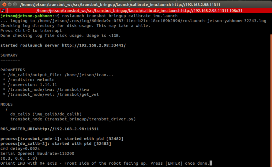
Start calibrate, we need calibrate the 6 axes of imu [X+, X-, Y+, Y-, Z+, Z-] in sequence. Then, click【Enter】key repeatedly until it appears the interface as shown below.
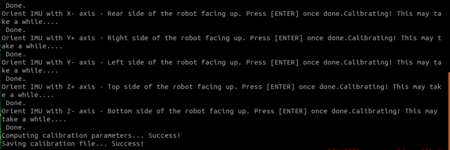
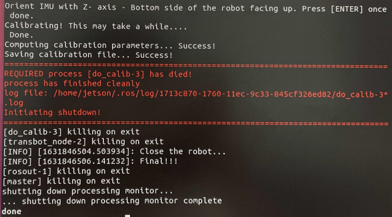
After the calibration is successful, the calibration information is stored in the YAML file. After the calibration is completed, it will exit automatically, as shown below.
View node graph
xxxxxxxxxxrqt_graph
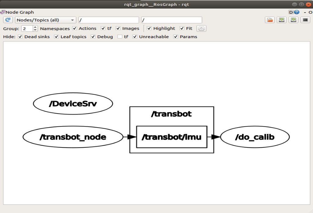
6.1.2、Related nodes
transbot_node
| Topic | Type | Parsing |
|---|---|---|
| /transbot/imu | sensor_msgs/Imu | The most primitive imu data of the car |
do_calib node
| / | Type | Defaults value | Parsing |
|---|---|---|---|
| Subscribed | sensor_msgs/Imu | /raw_imu | Original, uncalibrated IMU measurement |
| ~calib_file | string | "imu_calib.yaml" | The file where the calibration parameters will be written |
| ~measurements | int | 500 | Number of measurements collected for each direction |
| ~reference_acceleration | double | 9.80665 | Acceleration of gravity |
6.2、Linear speed calibration
Preparation:
- Measure a distance of 1 meter and make a mark.
- Place the cart to the starting point.
- Modify the parameter [linear_scale] in bringup.launch to 1.0.
Start the robot drive (robot side)
xxxxxxxxxxroslaunch transbot_bringup bringup.launch
Linear speed calibration (robot side or virtual machine side)
xxxxxxxxxxroslaunch transbot_bringup calibrate_linear.launch
As shown below.

Enable dynamic parameter adjustment (robot side or virtual machine side)
xxxxxxxxxxrosrun rqt_reconfigure rqt_reconfigure
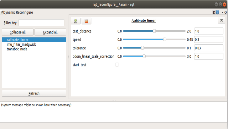
Click the square on the right side of [start_test] to start moving [test_distance]. At this time, observe whether the car really moves [test_distance]. If it is not the adjustment parameter [odom_linear_scale_correction], put the car back to the starting point to continue the test.
- test_distance:Test distance.
- speed:Test line speed. If the speed is too great, the inertia will be great.
- tolerance:The error in reaching the target. If the error is too small, it will jitter at the target position, otherwise, the error of reaching the target point will be large.
- odom_linear_scale_correction:Odometer zoom ratio.
- start_test:Start test.
After the test, remember the value of [odom_linear_scale_correction] and modify it to the value of the parameter [linear_scale] in bringup.launch.
6.3、Angular velocity calibration
Preparation:
- Place the car in a position where it is easy to rotate separately.
- Modify the parameter [angular_scale] in bringup.launch to 1.0.
Start the robot drive (robot side)
xxxxxxxxxxroslaunch transbot_bringup bringup.launch
Angular velocity calibration (robot side or virtual machine side)
xxxxxxxxxxroslaunch transbot_bringup calibrate_angular.launch
As shown below.

Enable dynamic parameter adjustment (robot side or virtual machine side)
xxxxxxxxxxrosrun rqt_reconfigure rqt_reconfigure
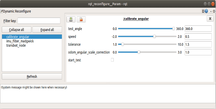
Click the square on the right side of [start_test] to start moving the [test_angle] distance. At this time, observe whether the car really moves [test_angle]. If it is not the adjustment parameter [odom_angule_scale_correction], return the car to the starting point to continue the test.
- test_angle: Test distance. It is not easy to be too big, the default is 360°.
- speed:Test the angular velocity. If the speed is too great, the inertia will be great.
- tolerance:The error in reaching the target. If the error is too small, it will jitter at the target position, otherwise, the error of reaching the target point will be large.
- odom_angule_scale_correction:Odometer zoom ratio.
- start_test:start test.
After the test, remember the value of [odom_angule_scale_correction] and modify it to the value of the parameter [angular_scale] in bringup.launch.