6 Robot state estimation
6 Robot state estimation 6.1 Start 6.1.1 Code reference path 6.1.1 Start 6.1.1 View tf tree and node graph 6.1.2 launch file analysis 6.1.3 imu_filter_madgwick 6.1.4 robot_localization
According to different models, you only need to set the purchased model in [.bashrc], X1 (ordinary four-wheel drive) X3 (Mike wheel) X3plus (Mike wheel mechanical arm) R2 (Ackerman differential) and so on. Section takes X3 as an example
Open the [.bashrc] file
sudo vim .bashrc
Find the [ROBOT_TYPE] parameter and modify the corresponding model
xxxxxxxxxxexport ROBOT_TYPE=X3 # ROBOT_TYPE: X1 X3 X3plus R2 X7
6.1 Start
6.1.1 Code reference path
xxxxxxxxxx~/yahboomcar_ws/src/yahboomcar_bringup/launch/bringup.launch
6.1.1 Start
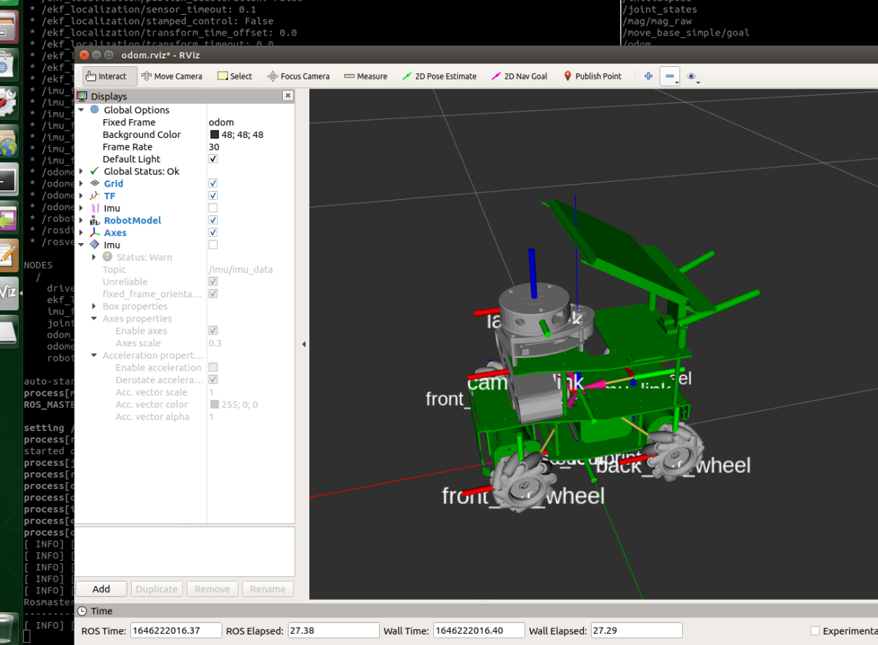
xxxxxxxxxxroslaunch yahboomcar_bringup bringup.launch use_rviz:=true
6.1.1 View tf tree and node graph
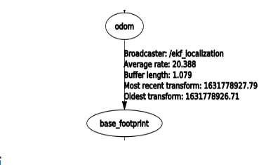
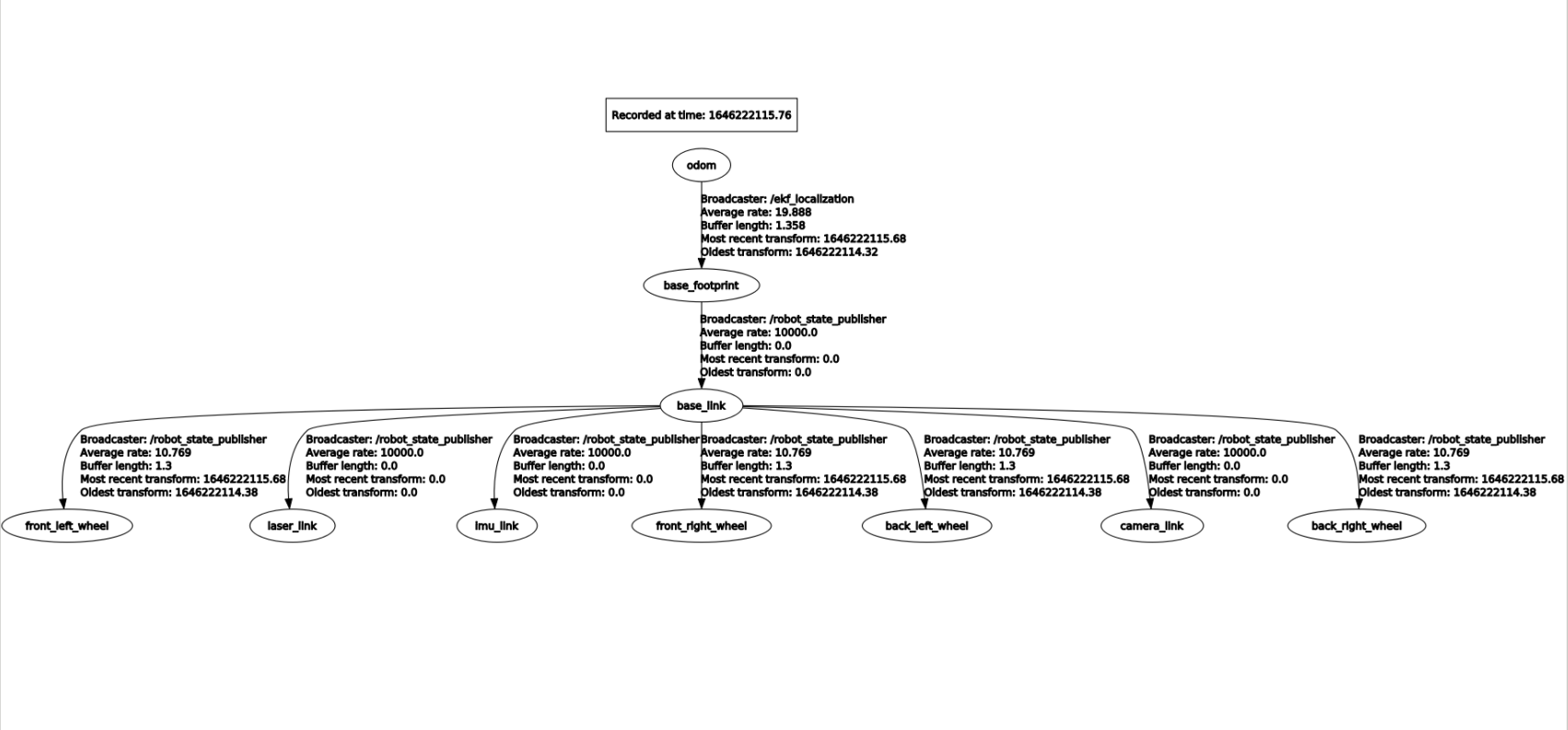
- view the TF tree
xxxxxxxxxxrosrun rqt_tf_tree rqt_tf_tree
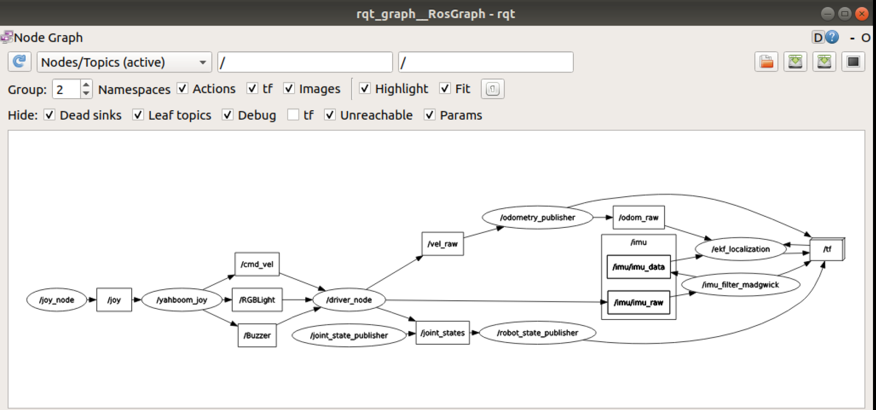
- view the node graph
xxxxxxxxxxrosrun rqt_graph rqt_graph
6.1.2 launch file analysis
In the bringup.launch file, there are several important nodes
- /drive_node
This node mainly publishes /imu/imu_raw and /vel_raw data, terminal input
xxxxxxxxxxrosnode info /driver_node
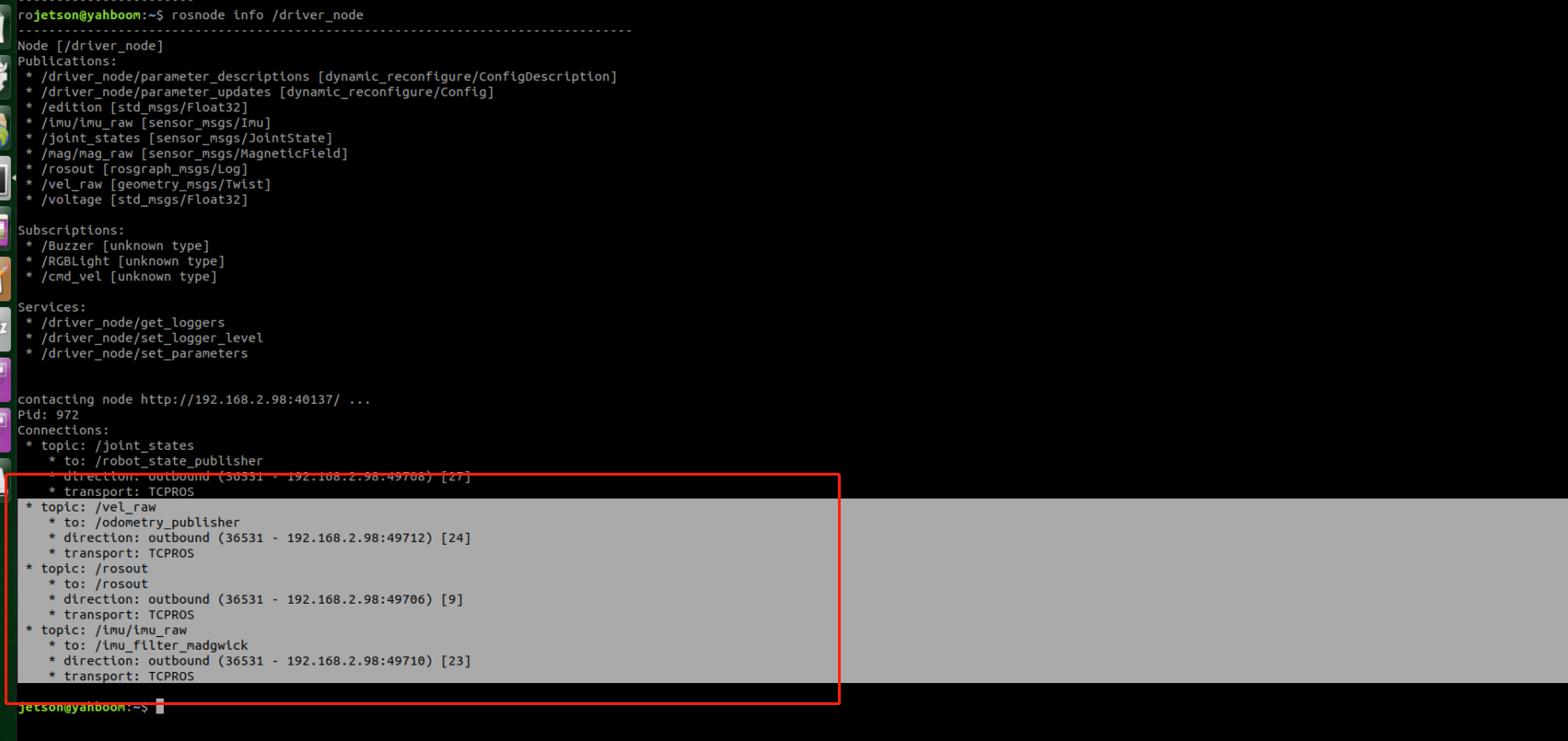
As can be seen,
- The /driver_node node publishes the /imu/imu_raw topic data to the /imu_filter_madgwick node, which filters and fuses the imu data;
- The /driver_node node publishes the /vel_raw topic data to the /odometry_publisher node. After the latter is integrated, the /odom_raw data is published;
- /odometry_publisher
This node mainly receives the vel_raw topic data sent by the /driver_node node, publishes the /odom_raw topic data to /ekf_localization, and publishes the /tf topic data to other nodes, terminal input,
xxxxxxxxxxrosnode info /odometry_publisher

- /imu_filter_madgwick
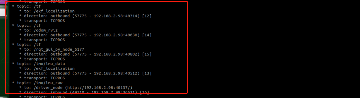
This node mainly filters and fuses imu data, and then publishes the processed /imu/imu_data topic data to the /ekf_localization node to receive and publish /tf data to other nodes, terminal input,
xxxxxxxxxxrosnode info /imu_filter_madgwick
- /ekf_localization
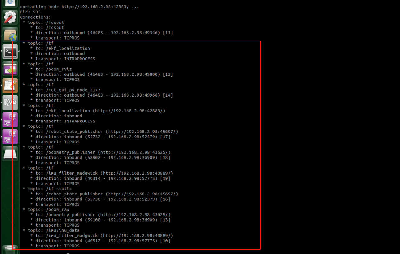
This node mainly integrates imu data and odom data and publishes tf data, terminal input,
xxxxxxxxxxrosnode info /ekf_localization
Next, we describe these nodes in detail.
6.1.3 imu_filter_madgwick
1 Introduction
IMU refers to a six-axis sensor that includes a gyroscope and an accelerometer. MARG refers to a nine-axis sensor that adds a magnetometer to the IMU.
xxxxxxxxxxIMU = gyroscope + accelerometerMARG (Magnetic, Angular Rate, and Gravity) = gyroscope + accelerometer + magnetometer
Madgwick is an Orientation Filter that filters and fuses raw data from IMU devices. It fuses angular velocity, acceleration, and (optional) magnetometer readings from generic IMU devices into orientation quaternions, and publishes the fused data on the IMU topic, regardless of the overall IMU integration process.
- topic
| / | topic name | type | Parse |
|---|---|---|---|
| Subscribed | /imu/data_raw | sensor_msgs/Imu | Messages of calibrated IMU data, including angular velocity and linear acceleration |
| Subscribed | /imu/mag | sensor_msgs/MagneticField | [Optional] Magnetometer, will be affected by magnetic fields |
| Published | /imu/data | sensor_msgs/Imu | Fused Imu information. |
- parameters
| parameter name | type | Defaults | Parse |
|---|---|---|---|
| ~gain | double | 0.1 | The gain of the filter. Higher values result in faster convergence but more noise. The lower the value, the slower the convergence, but the smoother the signal. Range: 0.0 to 1.0 |
| ~zeta | double | 0.0 | Gyro drift gain (about rad/s). Range: -1.0 to 1.0 |
| ~ mag_bias_x | double | 0.0 | Magnetometer bias (hard iron corrected) x-component. Range: -10.0 to 10.0 |
| ~mag_bias_y | double | 0.0 | Magnetometer bias (hard iron correction) y component. Range: -10.0 to 10.0 |
| ~ mag_bias_z | double | 0.0 | Magnetometer bias (hard iron correction) z component. Range: -10.0 to 10.0 |
| ~orientation_stddev | double | 0.0 | The standard deviation of the orientation estimate. Range: 0.0 to 1.0 |
| ~world_frame | string | "nwu" | World frame indicating direction (see REP-145). The old default was "nwu" (northwest up). New deployments should use "enu". Valid values: "nwu", "enu", "ned". |
| ~ use_mag | bool | true | Whether to use magnetic field data in data fusion. |
| ~use_magnetic_field_msg | bool | false | If set to true, Then subscribe /imu and /mag topics as sensor_msgs/MagneticField; If set to false (deprecated) Then use geometry_msgs/Vector3Stamped |
| ~fixed_frame | string | odom | Parent coordinate system to use in publishing |
| ~publish_tf | bool | false | Whether to publish the TF transform representing the direction of the IMU as the pose of the IMU; Use a fixed coordinate system as the parent coordinate system, The input imu information is used as the sub-coordinate system |
| ~reverse_tf | bool | false | If set to true, the transformation from the imu coordinate system to the fixed coordinate system is published, not the other way around. |
| ~constant_dt | double | 0.0 | The dt to use; if 0.0 (default) the dt dynamic value is calculated from the message start position. |
| ~publish_debug_topics | bool | false | If set to true, two debug topics are published. |
| ~stateless | bool | false | If set to true, the filtered orientation is not published. Instead, a stateless estimate of orientation is published based only on the latest accelerometer (and optional magnetometer) readings. for debugging. |
| ~remove_gravity_vector | bool | false | If set to true, the gravity vector is subtracted from the acceleration field in the published IMU message. |
6.1.4 robot_localization
1 Introduction
robot_localizationis a collection of state estimation nodes, each of which is an implementation of a nonlinear state estimator for a robot moving in 3D space. It includes two state estimation nodes ekf_localization_nodeand ukf_localization_node. in addition, robot_localizationsupply navsat_transform_node, it helps to integrate GPS data.
ekf_localization_nodeis Extended Kalman Filter . It uses an omnidirectional motion model to predict states in time and uses sensed sensor data to correct the predicted estimates.
ukf_localization_nodeis unscented Kalman filter . It uses a carefully chosen set of sigma points to project the state through the same motion model used in the EKF, and then uses these projected sigma points to recover the state estimate and covariance. This eliminates the use of the Jacobian matrix and makes the filter more stable. However, with ekf_localization_nodeIt is also more computationally heavy in comparison.
- topic
| / | topic name | type | Parse |
|---|---|---|---|
| Subscribed | /imu/data | sensor_msgs/Imu | Filtered imu information |
| Subscribed | /odom_raw | nav_msgs/Odometry | Odometer Information |
| Published | /odom | nav_msgs/Odometry | Fusion odometer information |
| Published | /tf | tf2_msgs/TFMessage | Coordinate system information |
- parameters
frequency: The true frequency (in Hz) at which the filter produces state estimates. Note: The filter does not start computing until it has received at least one message from one of the inputs.
[sensor] : For each sensor, the user needs to define this parameter according to the message type. Each parameter name is indexed from 0 (e.g. odom0, odom1, etc.) and must be defined in order (e.g. don't use pose0 and pose2 if pose1 is not already defined). The value of each parameter is the topic name for that sensor.
xxxxxxxxxxodom0: /odom_rawxxxxxxxxxximu0:/imu/data[sensor]_differential: For each sensor message defined above that contains pose information, the user can specify whether the pose variables should be integrated differentially. If the given value is set to true, then for the measurement taken at time t from the relevant sensor, we will first subtract the measurement at time t-1 and then convert the resulting value to velocity.
xxxxxxxxxx~odomN_differentialxxxxxxxxxx~imuN_differentialxxxxxxxxxx~poseN_differential[sensor]_relative: If this parameter is set to true, any measurements from this sensor will be fused relative to the first measurement received from this sensor. This is useful, for example, if you want the state estimate to always start at (0,0,0) and the roll, pitch and yaw angle values to be (0,0,0).
xxxxxxxxxx~odomN_relativexxxxxxxxxx~imuN_relativexxxxxxxxxx~poseN_relativetwo_d_mode: Set this to true if your robot operates in a flat environment and can ignore small changes in the ground (as reported by the IMU). It fuses all 3D variables (Z, roll, pitch and their respective velocity and acceleration) into a value of 0. This ensures that the covariances of these values don't explode, while ensuring that your robot's state estimate remains fixed on the XY plane.
odom0_config : [false, false, false, false, false, false, true, true, false, false, false, true, false, false, false]
The order of Boolean values is: [[X],[Y],[Z],[roll],[pitch],[yaw],[X ' ],[Y ' ],[Z ' ],[roll '],[pitch '],[yaw '],[X ''],[Y ''],[Z '']]. The user must specify which variables of these messages should be fused into the final state estimate.
- the published transformation
If the user's world_frameparameter is set to odom_framevalue, the conversion from odom_frameThe coordinate system given by the parameter is published to base_link_frameThe coordinate system given by the parameter. If the user's world_frameparameter is set to map_framevalue, the conversion from map_frameThe coordinate system given by the parameter is published to odom_frameThe coordinate system given by the parameter.
For example, we set to publish the transformation from the coordinate system given by the [odom_frame] parameter to the coordinate system given by the [base_link_frame] parameter.
xxxxxxxxxxodom_frame: odombase_link_frame: base_footprintworld_frame: odom