Positive Kinematics Analysis
This chapter deals with modeling and analysis of quadruped robots. By establishing a mathematical model for the single leg of the quadruped robot, the problem of forward and inverse solutions of single-leg kinematics is solved.
1.1 Kinematic parameters
In order to facilitate the design and modeling analysis of the whole machine, in the simulation software Webots, a simulation model is established according to the shape and structure of the traditional quadruped robot. As shown below.
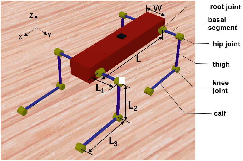
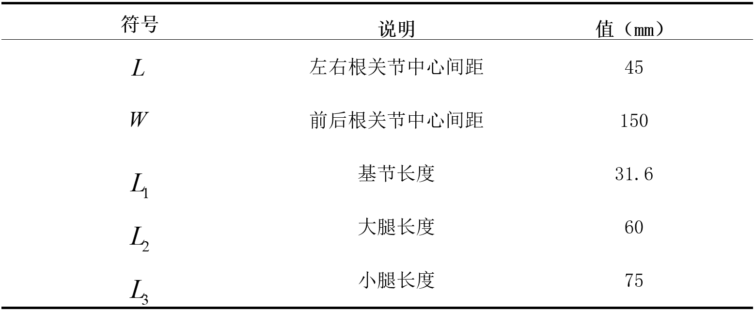
In the robot simulation model above, each leg of the quadruped robot has three degrees of freedom, from top to bottom are the root joint (controlling the shoulder), the hip joint (controlling the thigh), and the knee joint (controlling the calf). The link between the root joint and the hip joint is defined as the base joint, the link between the hip joint and the knee joint is defined as the thigh, and the link between the knee joint and the foot is defined as the calf. The structure, shape and size parameters of the four legs are exactly the same, and the robot parameters are shown in the figure.
1.2 Modeling of single leg positive kinematics
Kinematics analysis is the basis of free gait planning for quadruped robots, which can be divided into positive kinematics solution and inverse kinematics solution. The positive kinematics solution in robotics means that, given the parameters such as the joint angle of the manipulator and the length of the connecting rod, the position and attitude of the end are solved;The inverse kinematics solution means that given the position and attitude of the end of the manipulator, the motion parameters of each joint corresponding to the manipulator are solved.
The commonly used kinematic modeling methods of quadruped robots include D-H method, Lie algebra method, etc.
The D-H method is a general method proposed by Denavit and Hartenberg for solving robot kinematics. The idea of the D-H method is to establish a coordinate system on all the links of the robot arm, and use the transformation matrix to describe the spatial transformation relationship between the two adjacent links, which can be applied to the forward kinematics scene of a series mechanism with any degree of freedom.But when there are too many degrees of freedom, the D-H method is used to solve the inverse kinematics solution, and there will be problems that the solution is not unique and the analytical solution of the inverse kinematics cannot be obtained. However, since this robot dog has only three degrees of freedom per leg, the D-H method can be used for kinematic modeling.
Since the structure of the four legs of the quadruped robot is completely symmetrical, only the kinematic modeling of the single leg can be performed. This paper takes the left front leg as an example, as shown in the figure below, firstly establish the coordinate system of the whole machine and the coordinate system of the single-leg link, and then solve the forward kinematics of the single leg.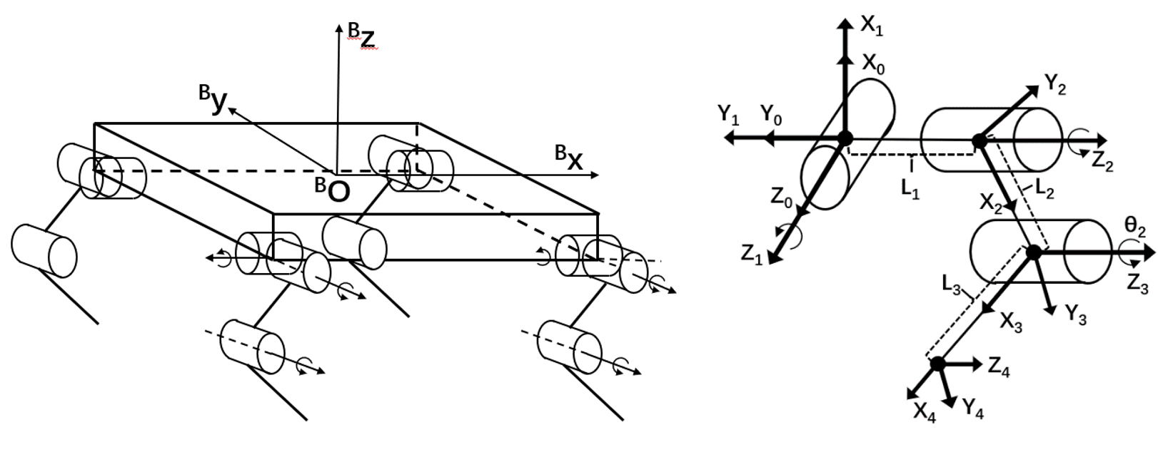
The parameters of the left front leg link coordinate system are shown in the following figure.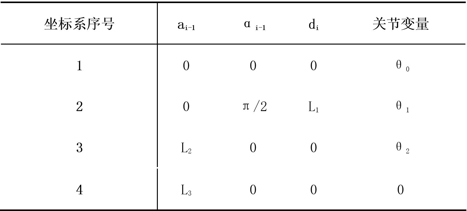
Among them, the connecting rod length a~i−1~represents the distance between the two joint axes, that is, the length of the common vertical line between z~i−1~ and z~i~; The torsion angle α~i−1~ of the connecting rod represents the angle between the two joint axes, that is, the angle of rotation from z~i−1~ to z~i~ around x~i−1~;The connecting rod distance d~i~ represents the distance from x~i−1~ to x~i~ along z~i~; the connecting rod rotation angle represents the rotation angle from to along.The spatial relationship between two adjacent connecting rod coordinate systems {i} and {i−1} is described by the transformation matrix ^i−1^~i~T.It is obtained by the following four sub-transformations: Rotation α~i−1~ around the x~i−1~ axis; Translation α~i−1~ along the x~i−1~ axis; Rotation θ~ around the z~i~ axis i~; Translate d~i~ along the z~i~ axis; c can obtain the expression of the transformation matrix ^i−1^~i~T between adjacent connecting rod coordinate systems: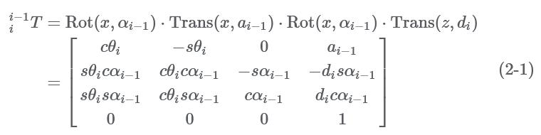
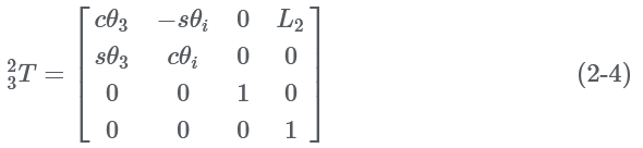
Substitute the parameters of the coordinate system in the above figure into formula (2-1), and the transformation matrix between two adjacent coordinate systems can be obtained, as follows: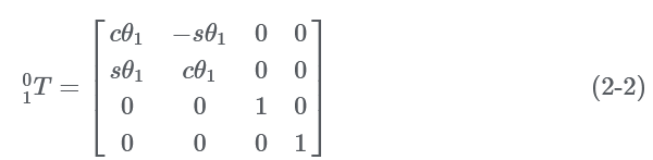

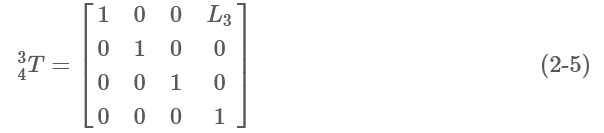
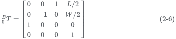
From formula (2-2) to formula (2-6), the transformation matrix of the foot end coordinate system {O4} relative to the body coordinate system {B} can be obtained:
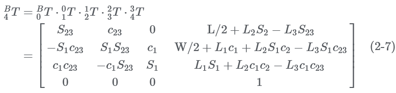
B4T can be decomposed into a rotating part and a moving part, as shown in the following formula:
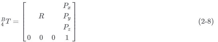
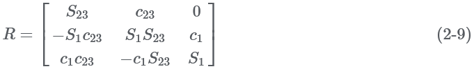
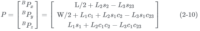
In formula (2-8), R represents the posture of the foot end coordinate system relative to the body coordinate system, and the foot end posture is not considered in the plane free gait planning problem, and P represents the position of the foot end in the body coordinate system. Equation (2-10) is the positive kinematics solution of the left front leg of the quadruped robot. If the three joint angles of the leg are known, the position of the foot end relative to the coordinate system can be obtained by bringing it into the equation.
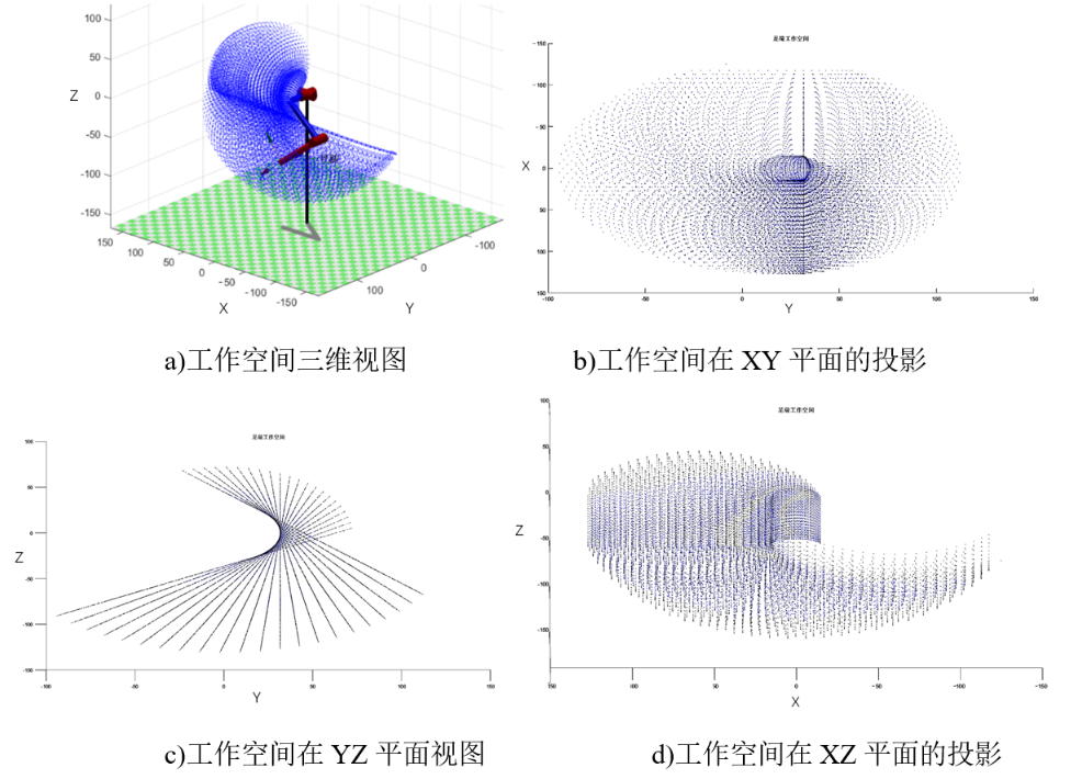
It is known that the root joint angle range is [−50∘, 90∘], the hip joint angle range is [−90∘, 80∘], and the knee joint angle range is [−60∘, 45∘]. Use the robotics toolbox in matlab to create a single-leg model of a quadruped robot, and traverse each joint angle within a limited range to obtain the foot end workspace, as shown in Figure 2-3.