8.karto mapping algorithm
8.karto mapping algorithm8.1 Introduction 8.2 Use 8.2.1 Start 8.2.2 Control the robot 8.2.3 Map save 8.3 Topics and Services 8.4 configuration parameters 8.5 TF transformation
karto : http://wiki.ros.org/slam_karto
map_server: https://wiki.ros.org/map_server
8.1 Introduction
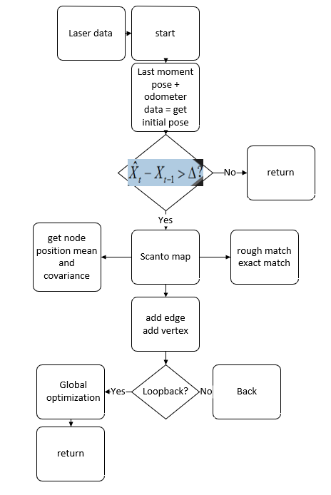
Karto is a 2D laser SLAM solution based on sparse graph optimization with loop closure detection. The graph optimization method uses the mean value of the graph to represent the map, and each node represents a position point of the robot trajectory and a sensor measurement data set. Karto uses the spa(karto_slam) or g2o(nav2d) optimization library, and the front-end and back-end are single-threaded.
The ROS version of Karto_SLAM, which employs the Spare Pose Adjustment(SPA) related to scan matching and loop closure detection. The more landmarks there are, the greater the memory requirements. However, the graph optimization method has greater advantages in mapping compared to other methods in a large environment, because it only contains the robot pose of the point, and then the map is obtained after the pose is obtained.
overall program framework
8.2 Use
Note: When building a map, the slower the speed, the better the effect(note that if the rotation speed is slower), the effect will be poor if the speed is too fast.
According to different models, you only need to set the purchased model in [.bashrc], X1(ordinary four-wheel drive) X3(Mike wheel) X3plus(Mike wheel mechanical arm) R2(Ackerman differential) and so on. Section takes X3 as an example
Open the [.bashrc] file
sudo vim .bashrc
Find the [ROBOT_TYPE] parameter and modify the corresponding model
xxxxxxxxxxexport ROBOT_TYPE=X3 # ROBOT_TYPE: X1 X3 X3plus R2 X7
8.2.1 Start
Start command(robot side), for the convenience of operation, this section takes [mono + laser + yahboomcar] as an example.
xxxxxxxxxxroslaunch yahboomcar_nav laser_bringup.launch # laser + yahboomcarroslaunch yahboomcar_nav laser_usb_bringup.launch # mono + laser + yahboomcarroslaunch yahboomcar_nav laser_astrapro_bringup.launch # Astra + laser + yahboomcar
Mapping command(robot side)
xxxxxxxxxxroslaunch yahboomcar_nav yahboomcar_map.launch use_rviz:=false map_type:=karto
- [use_rviz] parameter: whether to enable rviz visualization.
- [map_type] parameter: set the mapping algorithm [karto].
Open the visual interface(virtual machine side)
xxxxxxxxxxroslaunch yahboomcar_nav view_map.launch
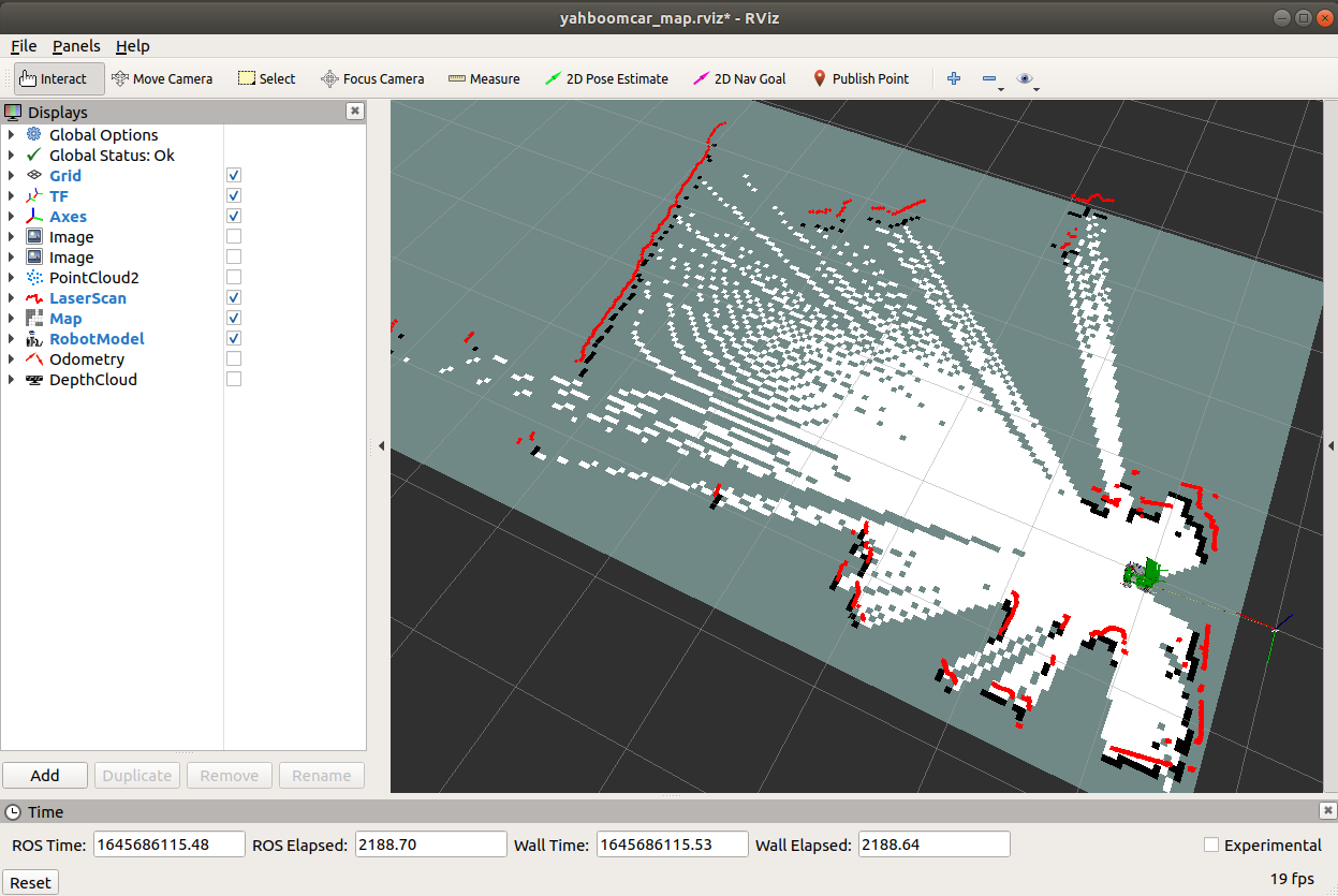
The gap at the back of the robot is due to the occlusion of the installation position of the display screen, so a certain range of Lidar data is shielded. The shielding range can be adjusted or not shielded according to the actual situation. For details, see [01. Lidar Basic Course].
8.2.2 Control the robot
- The keyboard controls the movement of the robot
xrosrun teleop_twist_keyboard teleop_twist_keyboard.py # system integrationroslaunch yahboomcar_ctrl yahboom_keyboard.launch # custom
- The handle controls the movement of the robot
Make the robot walk all over the area to be built, and the map is as closed as possible.
There may be some scattered points during the mapping process. If the mapping environment is well closed and regular, the movement is slow, and the scattering phenomenon is much smaller.
8.2.3 Map save
xrosrun map_server map_saver -f ~/yahboomcar_ws/src/yahboomcar_nav/maps/my_map # The first waybash ~/yahboomcar_ws/src/yahboomcar_nav/maps/map.sh # second way
The map will be saved to ~/yahboomcar_ws/src/yahboomcar_nav/maps/ folder, a pgm image, a yaml file.
map.yaml
ximage : map.pgmresolution : 0.05origin : [-15.4,-12.2,0.0]negate : 0occupied_thresh : 0.65free_thresh: 0.196
Parameter parsing:
- image: The path of the map file, which can be an absolute path or a relative path
- resolution: the resolution of the map, m/pixel
- origin: The 2D pose(x, y, yaw) of the lower left corner of the map, where yaw is rotated counterclockwise(yaw=0 means no rotation). Many parts of the system currently ignore the yaw value.
- negate: whether to reverse the meaning of white/black, free/occupy(the interpretation of the threshold is not affected)
- occupied_thresh: Pixels with an occupancy probability greater than this threshold will be considered fully occupied.
- free_thresh: Pixels with an occupancy probability less than this threshold will be considered completely free.
8.3 Topics and Services
| Topic subscription | type | describe |
|---|---|---|
| scan | sensor_msgs/LaserScan | Depth data from lidar scans |
| tf | tf/tfMessage | Used to convert between lidar coordinate system, base coordinate system, and odometer coordinate system |
| Topic release | type | describe |
| map_metadata | nav_msgs/MapMetaData | Publish map Meta data |
| map | nav_msgs/OccupancyGrid | Publish map raster data |
| visualization_marker_array | visualisation_msgs/MarkerArray | Post pose diagram |
| Serve | type | describe |
| dynamic_map | nav_msgs/GetMap | Get map data |
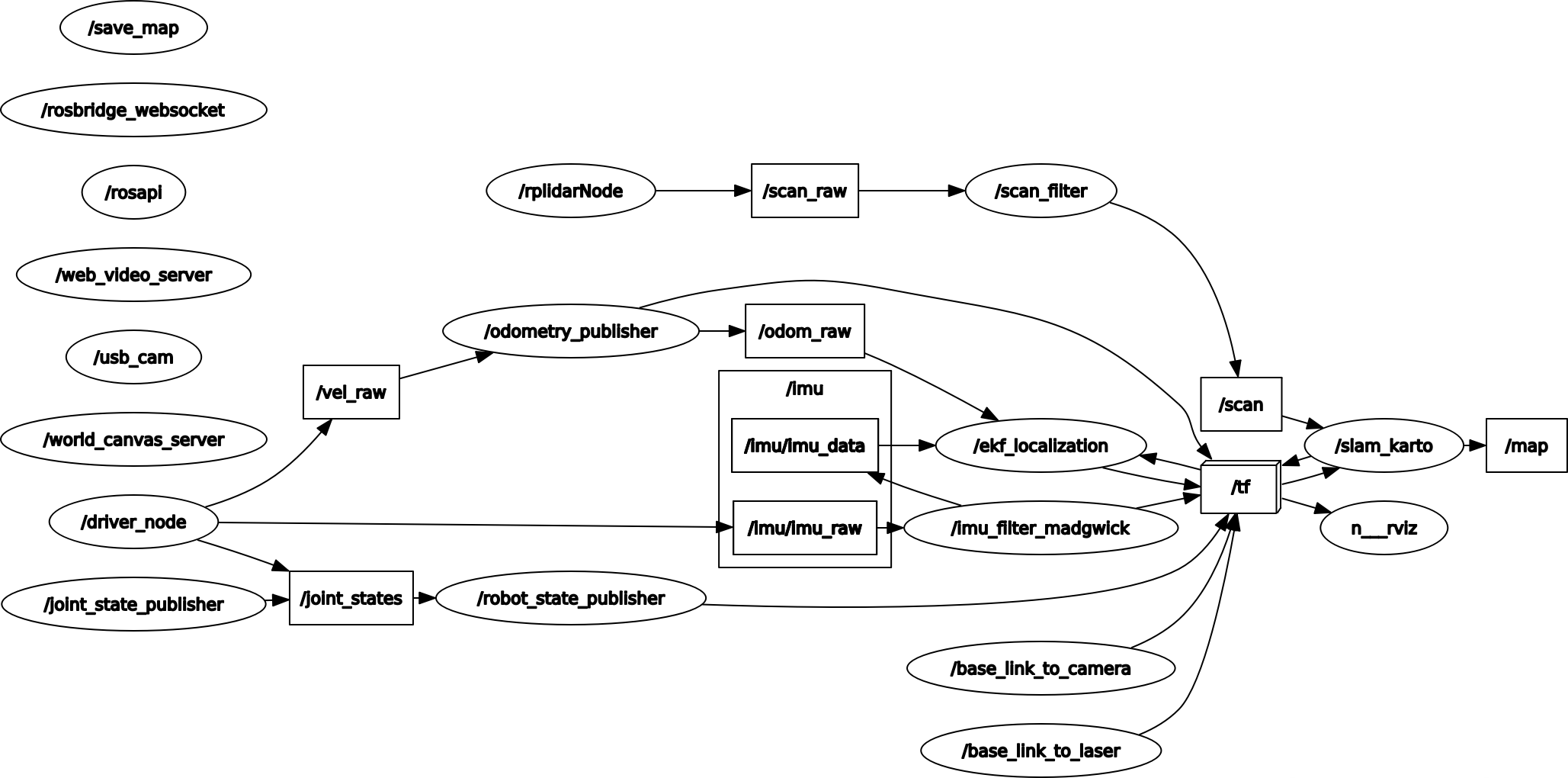
Node view
xxxxxxxxxxrqt_graph
8.4 configuration parameters
- General parameters
| parameter | type | Defaults | illustrate |
|---|---|---|---|
| ~base_frame | string | "base_link" | Robot base coordinate system |
| ~map_frame | string | "map" | map coordinate system |
| ~odom_frame | string | "odom" | Odometer Coordinate System |
| ~throttle_scans | int | 1 | Process 1 every so many scans(set it to a higher number to skip more scans) |
| ~map_update_interval | float | 5.0 | The interval in seconds between map updates. Lowering this number updates the occupancy grid more frequently, but increases the computational load. |
| ~resolution | float | 0.05 | Map resolution(meters per occupied grid block) |
| ~delta | float | 0.05 | Map resolution(meters per occupied grid block). Same as resolution. Defined for compatibility with gmapping parameter names. |
| ~transform_publish_period | float | 0.05 | The interval(in seconds) between transition publications. |
| use_scan_matching | bool | true | Whether to use the scan matching algorithm, generally set to true, the mapper algorithm can correct the noise and error of the odometer and the laser. In some simulation environments with accurate sensor data, the scan matching algorithm will get worse results(because of the use of Gaussian blur, which reduces the observation confidence of high-precision sensors), it is recommended to close(add noise to the simulation environment). |
| use_scan_barycenter | bool | true | Use the centroids of the scan endpoints to define the distance between scans. |
| minimum_travel_distance | double | 0.2 | Sets the minimum travel between scans. |
| minimum_travel_heading | double | deg2rad(10) = 0.087266461 | Sets the minimum angle between scans. |
| scan_buffer_size | int | 70 | Set the length of ScanBuffer, approximately equal to scan_buffer_maximum_scan_distance/minimum_travel_distance |
| scan_buffer_maximum_scan_distance | double | 20.0 | Setting the maximum length of ScanBuffer is similar to Size |
| link_match_minimum_response_fine | double | 0.8 | Set minimum response threshold for minimum scans connections |
| link_scan_minimum_distance | double | 10.0 | Set the maximum distance of scans between two connections. If it is greater than this value, the response threshold of the two will not be considered. |
| loop_search_maximum_distance | double | 4.0 | Loopback detection maximum distance. Scans less than this distance from the current position will be considered matched loop closures. |
| do_loop_closing | bool | true | Whether to enable loopback detection |
| loop_match_minimum_chain_size | int | 10 | Loop detection minimum chain size |
| loop_match_maximum_variance_coarse | double | math::Square(0.4)=0.16 | The maximum covariance value of rough matching during loopback matching, if it is less than this value, it is considered a feasible solution |
| loop_match_minimum_response_coarse | double | 0.8 | The minimum response of coarse matching during loopback matching. If the response value is greater than this value, coarse-precision loopback optimization will start. |
| loop_match_minimum_response_fine | double | 0.8 | The loopback matches the minimum response threshold, and if it is greater than this value, the high-precision starts |
- Correction parameters
| parameter | type | Defaults | illustrate |
|---|---|---|---|
| correlation_search_space_dimension | double | 0.3 | Set the search range size of the Correlation Grid |
| correlation_search_space_resolution | double | 0.01 | Set the resolution of the Correlation Grid |
| correlation_search_space_smear_deviation | double | 0.03 | Set the Correlation Grid blur level |
- loopback parameters
| parameter | type | Defaults | illustrate |
|---|---|---|---|
| loop_search_space_dimension | double | 8.0 | Loopback detection space range size |
| loop_search_space_resolution | double | 0.05 | Loop Closure Detection Spatial Resolution |
| loop_search_space_smear_deviation | double | 0.03 | Loop closure detection blur level |
- Scan Matcher parameters
| parameter | type | Defaults | illustrate |
|---|---|---|---|
| distance_variance_penalty | double | sqrt(0.3)=0.09(less than 1.0) | Compensation factor for odometer during scan-matching |
| angle_variance_penalty | double | sqrt(deg2rad(20))=0.17453292 | Compensation coefficient for angle during scan-matching |
| fine_search_angle_offset | double | deg2rad(0.2) = 0.0017453292 | Refine search angle range |
| coarse_search_angle_offset | double | deg2rad(20) = 0.17453292 | Rough search angle range |
| coarse_angle_resolution | double | deg2rad(2) = 0.017453292 | Coarse search angle resolution |
| minimum_angle_penalty | double | 0.9 | Minimum angle penalty |
| minimum_distance_penalty | double | 0.5 | minimum distance penalty |
| use_response_expansion | bool | false | Whether to increase the search scope if no good matches are found |
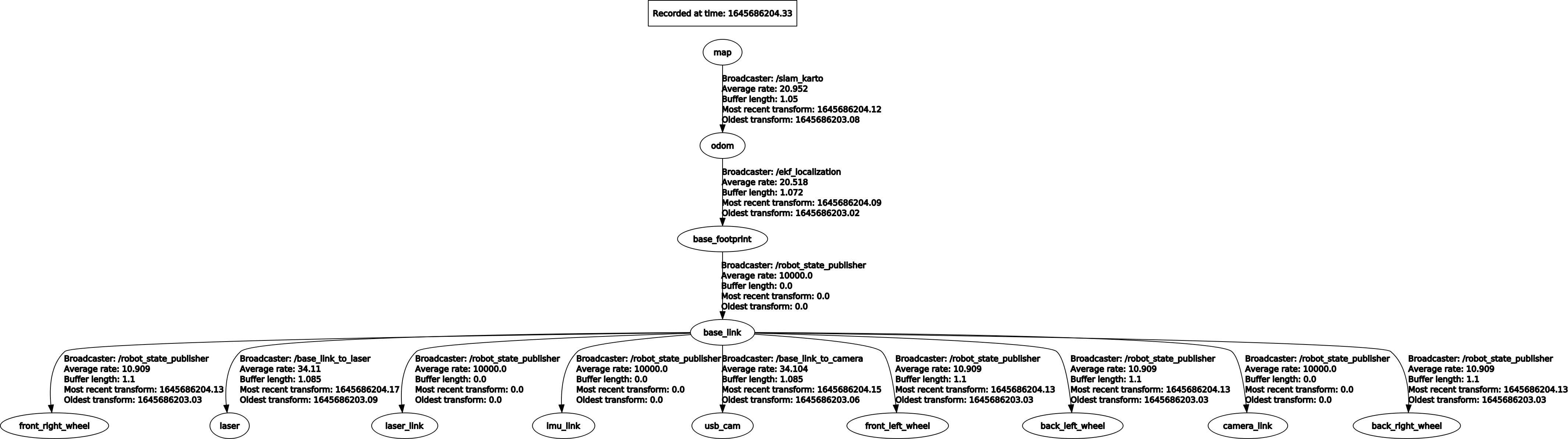
8.5 TF transformation
| Required TF Transform | describe |
|---|---|
| laser-->base_link | Usually a fixed value, the transformation between the lidar coordinate system and the base coordinate system is generally published by robot_state_publisher or static_transform_publisher |
| base_link-->odom | The transformation between the map coordinate system and the robot's odometer coordinate system to estimate the robot's pose in the map |
| Published TF Transform | describe |
| map-->odom | The current estimate of the robot pose within the map frame(only provided if parameter "pub_map_odom_transform" is true). |
View tf tree
xxxxxxxxxxrosrun rqt_tf_tree rqt_tf_tree