PID control robot movement
PID control robot movement 1. Experimental purpose 2. configuration pin information 3. Analysis of the experimental flow chart 4. core code explanation 5. hardware connection 6. Experimental effect
1. Experimental purpose
Control the movement of the robot, and control the running speed of the robot through the PID algorithm.
Since different models require different drive codes, here we only take the Mecanum wheel trolley as an example.
2. configuration pin information
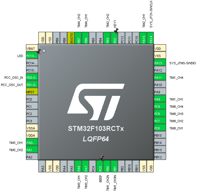
- Import the ioc file from the Encoder project and name it Car_Motion.
No additional content is required, and the final chip configuration pins are shown in the following figure:
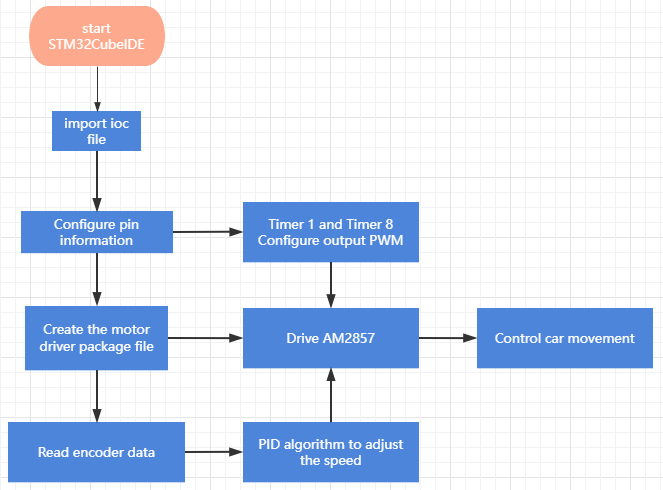
3. Analysis of the experimental flow chart
4. core code explanation
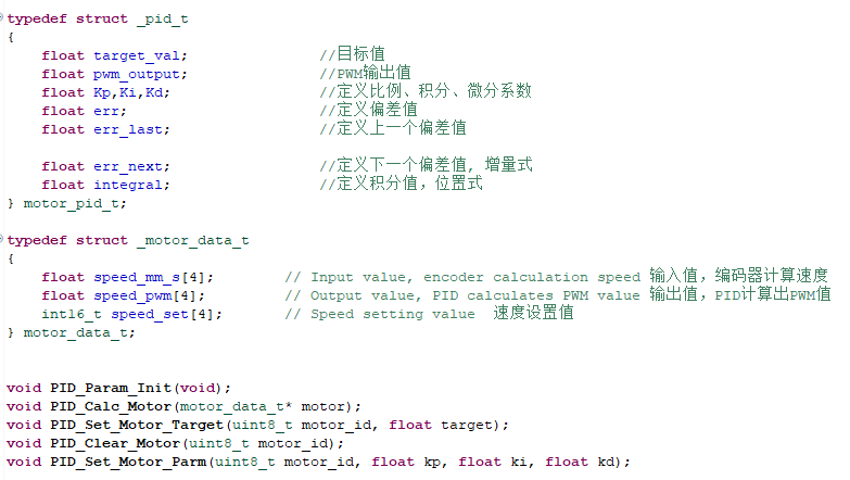
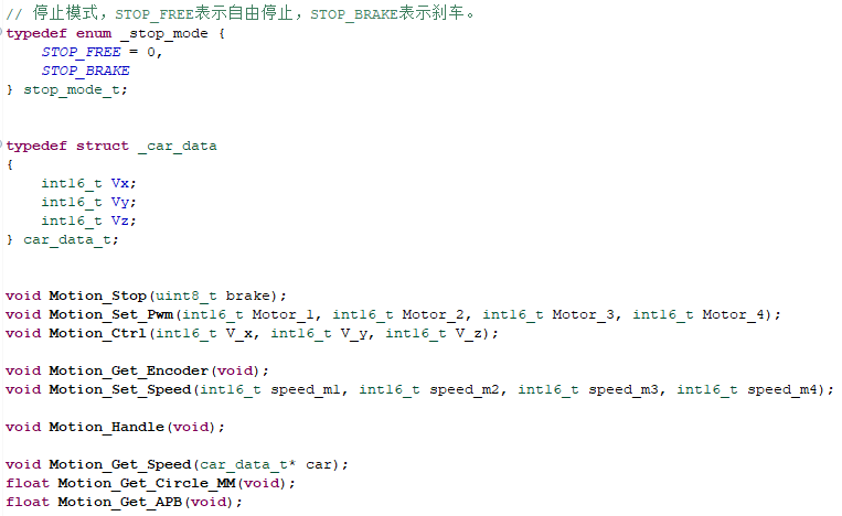
- Create new bsp_pid.h and bsp_pid.c, and add the following content to bsp_pid.h:
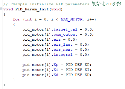
- Create the following content in the bsp_pid.c file:
Initialize PID parameters:
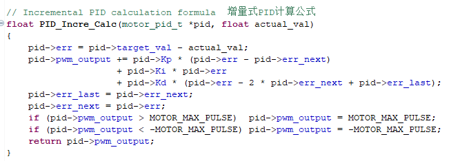
- Calculation formula of incremental PID.
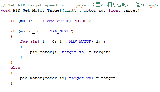
- Set the target value.
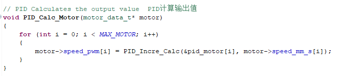
- Calculate the PWM output value through PID calculation.
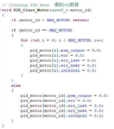
- Clear the PID parameter data.
- Create new bsp_motion.h and bsp_motion.c files.
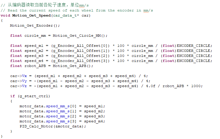
- Get and calculate the speed of the trolley from the encoder.
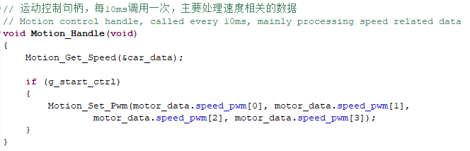
- Re-update the PWM data of the motor according to the speed value, so as to achieve the effect of speed regulation.
5. hardware connection
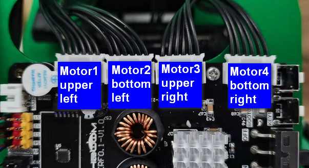
The motor connecting line needs to be connected to the corresponding motor as shown in the figure below, otherwise it may cause the problem that the program does not match the phenomenon. Motor 1 corresponds to the motor in the upper left corner of the body, Motor 2 corresponds to the motor in the lower left corner, Motor 3 corresponds to the motor in the upper right corner, and Motor 4 corresponds to the motor in the lower right corner.
Since the power of the motor is relatively large, the expansion board should not be powered by USB 5V directly, but must be powered by DC 12V.
6. Experimental effect
Since the motor will turn when started, please stand up the trolley before the experiment, and the motor wheels are suspended in the air to avoid rampage.
After the program is programmed, the LED light flashes every 200 milliseconds. Press the button KEY1 once, the car moves forward, and press the KEY1 button again to stop the car.