Application of lidar on STM32
Application of lidar on STM321.Introduction to lidar1.1Product feature1.2 Application scenario1.3 Interface definition2.Important communication protocols2.1 Start ranging2.2 Stop ranging2.3 Set output frequency2.4 Set baud rate3.Connection mode of stm32 and SDM153.1Wiring instructions4.Experimental result
1.Introduction to lidar
YDLIDAR SDM15 lidar is a high-performance single-point lidar (hereinafter referred to as SDM15). This product is based on the principle of time-of-flight distance measurement, combined with relevant optical, electrical and algorithm design, to achieve high-precision laser distance measurement and output high frame rate point cloud data. It can be used for UAV altitude determination, robot obstacle avoidance, navigation, etc.
1.1Product feature
➢ Small ranging error and good ranging stability ➢ The range scanning frequency is high, and internal high sampling and filtering pretreatment can be configured ➢ Output frequency can be flexibly configured according to requirements ➢ Long detection distance, up to 15 meters ➢ The detection distance is small, and the nearest detectable distance is 50mm ➢ Laser power meets FDA Class I safety standards ➢ Service life 10000h
1.2 Application scenario
➢ UAV height setting and obstacle avoidance ➢ Robot obstacle avoidance ➢ Intelligent equipment obstacle avoidance ➢ Navigation and obstacle avoidance of household service robot/sweeping robot
1.3 Interface definition
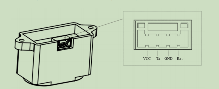 VCC: power supply interface (positive) 5V (The measured data below 5V is inaccurate, and the laser radar may be burnt out if it is higher than 5V)
TX: output port of communication serial port
RX: input port of communication serial port
GND: power supply interface (negative) 0V
VCC: power supply interface (positive) 5V (The measured data below 5V is inaccurate, and the laser radar may be burnt out if it is higher than 5V)
TX: output port of communication serial port
RX: input port of communication serial port
GND: power supply interface (negative) 0V
2.Important communication protocols
| Package | type | Length | Data segment | Check code |
|---|---|---|---|---|
| 2 bytes | 1 bytes | 1 bytes | N bytes | 1 bytes |
The communication protocol used in the provided routine is as follows: ➢ Baotou: SDM_ The message header flag of 15 is 0x55AA; ➢ Package type: the type of system command, as shown in the table; ➢ Data length: refers to the length of response data; ➢ Data segment: the response content under different system commands and different data content are fed back. The data format is also different, and the length is determined by the data length. ➢ Check code: check code, the sum of all other data except the check code, taking the lower 8 digits;
2.1 Start ranging
stm32 send :0xAA 0x55 0x60 0x00 0x5F SDM15 response :0xAA 0x55 0x60 0x04 Distance (low 8 bits) Distance (high 8 bits) Strength (8 bits) Interference (8 bits) Check code (sum of previous data)
2.2 Stop ranging
stm32 send : 0xAA 0x55 0x61 0x00 0x60 SDM15 response:0xAA 0x55 0x61 0x00 0x60
2.3 Set output frequency
stm32 send: 0xAA 0x55 0x64 0x01 Set frequency check code SDM15 response: 0xAA 0x55 0x64 0x01 Set frequency check code
The frequency of the set frequency check code is: 10hz, 100hz, 200hz, 500hz, 1000hz, 1800hz output frequency, corresponding to code 0-5 (default is 100hz)
2.4 Set baud rate
stm32 send: 0xAA 0x55 0x66 0x01 Set frequency check code SDM15 response: 0xAA 0x55 0x66 0x01 Set frequency check code
Baud rate set: 230400, 460800, 512000, 921600, 1500000 correspond to code 0-4 (default is 460800). After the baud rate is set, it takes effect after being powered on again
3.Connection mode of stm32 and SDM15
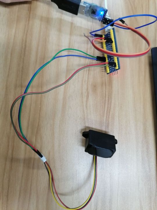
3.1Wiring instructions
This routine uses usart1 and usart2 for experiments
- USART1 function: communicate with the computer - output range, signal strength, jamming signal and baud rate of 115200 of the received radar PA9 of STM32 is connected to RXD of usb to ttl module PA10 of STM32 is connected to TXD of usb to ttl module GND of STM32 is connected to GND of usb to ttl module VCC can be disconnected
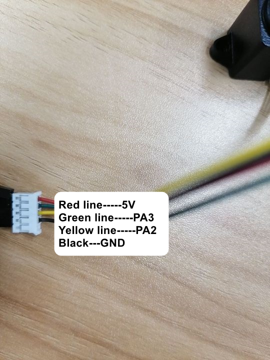
- USART2 function: communicate with laser radar, with baud rate of 460800 (default value) PA2 of STM32 is connected to RXD of SDM15 module PA3 of STM32 is connected to TXD of SDM15 module GND of STM32 is connected to GND of SDM15 module The 5V pin of STM32 is connected to the VCC of SDM15 module (provided that STM32 needs to be connected to 5V power supply, otherwise the radar power cannot reach 5V, resulting in inaccurate measured data.)
- This experiment needs a USB to TTL module. If not, you need to buy it by yourself.
4.Experimental result
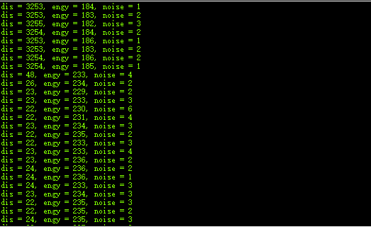
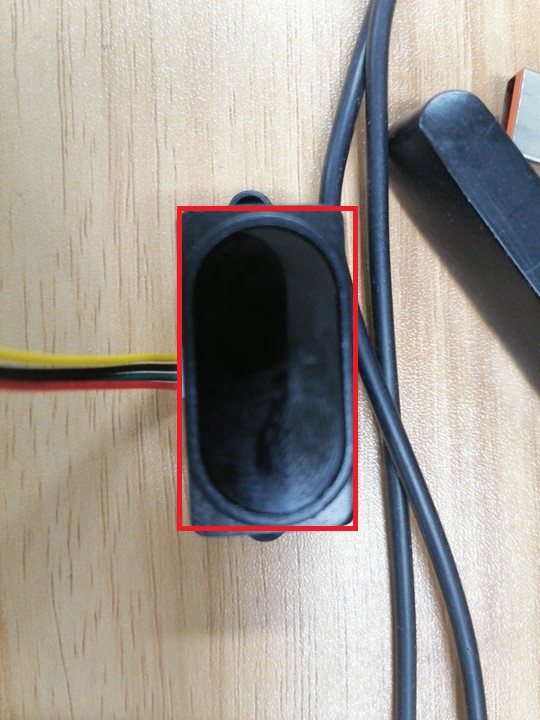 Use objects to block the part as shown in the figure. The data of the experimental results are shown in the figure below (dis: distance, intensity: intensity, noise: interference)
In addition, the light on the stm32 board will change its state every time it receives the range data from the radar to achieve the flashing effect.
Use objects to block the part as shown in the figure. The data of the experimental results are shown in the figure below (dis: distance, intensity: intensity, noise: interference)
In addition, the light on the stm32 board will change its state every time it receives the range data from the radar to achieve the flashing effect.