3.5.PWM control breathing light experiment
1. learning target
1.Learn the principle of PWM control breathing light
2.Output a PWM signal through CH4 of TIM4 to control the LED indicator light from dark to bright, and then from bright to dark, similar to human breathing.
Introduction to PWM Principle:
PWM is the abbreviation of Pulse Width Modulation, which means pulse width modulation, referred to as pulse width modulation. It is a very effective technology that uses the digital output of the microprocessor to control the analog circuit. It has the advantages of simple control, flexibility and good dynamic response, so it has become the most widely used control method in power electronics technology. Its application fields include Measurement, communication, power control and conversion, motor control, servo control, dimming, switching power supply, and even some audio amplifiers, so learning PWM has very important practical significance.
In fact, we can also understand that PWM is a method of digitally encoding the analog signal level. Through the use of high-resolution counters, the duty cycle of the square wave is modulated to encode the level of a specific analog signal. The PWM signal is still digital because at any given moment, full-scale DC power is either fully present (ON) or completely absent (OFF). A voltage or current source is applied to an analog load in a repetitive pulse sequence of ON or OFF. When it is on, it is when the DC power supply is added to the load, and when it is off, it is when the power supply is disconnected. Any analog value can be encoded using PWM as long as the bandwidth is sufficient.
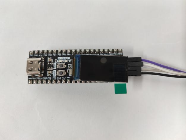
2.Hardware wiring connection
The timer pin used in this experiment is PB9, and the corresponding timer channel is TIM4_CH4. Since the PB9 pin does not have an LED light, in order to observe the effect of the breathing light, we connect PB9 and PC13 with a DuPont line, and directly use the onboard led light.
Note: 1. Connect the pins after successfully downloading the program; 2. Dupont wires need to be purchased separately.
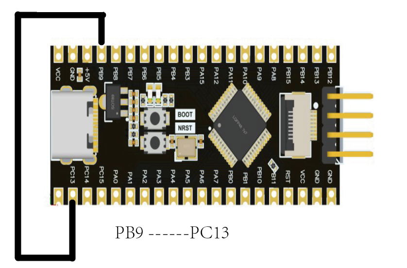
Wiring Reference Diagram
3. program analysis
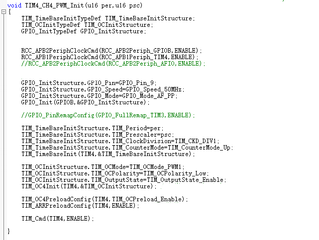
The PWM output frequency is unchanged, but the value in the CCR register is changed, and the change of this value will cause the duty cycle of the PWM output signal to change. The duty cycle is actually the ratio of the high level time to the period in a cycle, and changing this ratio can control the time when the io pin outputs high and low levels, so the PWM signal can be output through CH4 of TIM4 to realize the control of the LED breathing light.
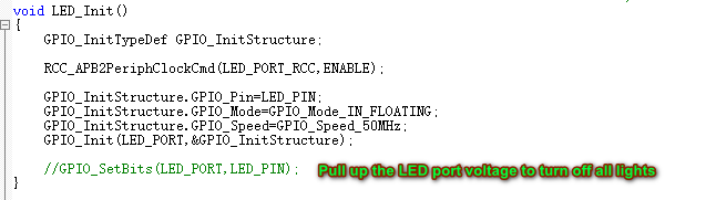
LED initialization code:
PWM initialization code:
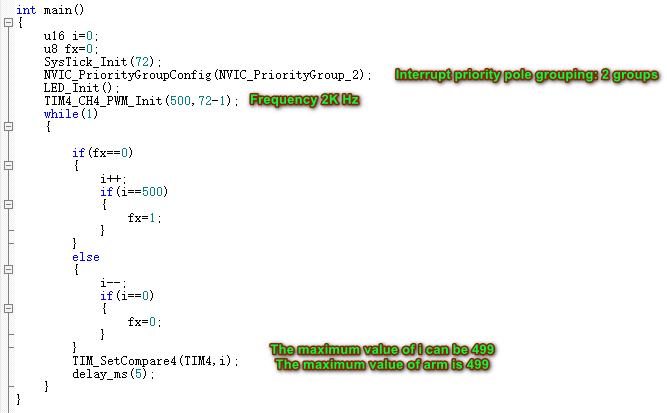
Main function main.c file code:
4. Experimental phenomena
After the program download is complete, we can see that the LED light on the STM32 motherboard is slowly turning on and off, showing the effect of a breathing light.