4 PWM breathing light experiment
4 PWM breathing light experiment 4.1 experimental target 4.2 experimental procedure 4.3 experimental results 4.4 the experiments are summarized
4.1 experimental target
This lesson is mainly for learning microPython control PWM output function.
The present experiments the reference code path is: CanMV\03-Hardware\pwm.py
4.2 experimental procedure
Module factory firmware has been integrated PWM output module, if you download the other firmware, please burn back to the factory firmware and then perform the experiment.
By machine import PWM and Timer.
from machine import Timer, PWMimport time
Since the PWM signal needs to be the source of self-timer, so create a new timer object, Set the parameters for timer 0, channel 0, the PWM mode.
xxxxxxxxxxtim = Timer(the Timer. TIMER0, Timer. CHANNEL0, mode=Timer. MODE_PWM)
By specifying the parameters of a new PWM object.
xxxxxxxxxxpwm = the machine. PWM(tim, freq, duty, pin, enable=True)
tim: Each PWM rely on a timer to generate a waveform, so there will need to pass a timer object the timer object must be initialized must be specified when the timer ID and channel numberfreq: PWM waveform frequencyduty: PWM duty cycle, refers to the high level for the entire period the percentage of values: [0,100][pin]: PWM output pin. The actual physical pin of the IO number.enable: Whether to immediately begin generating a waveform, the default bitTrue, And the object is generated immediately after the start at the specified pin to generate a PWM waveform
Create a while loop, modify the duty cycle of the duty of values, so that the cycle changes from 0 to 100, from 100 down to 0, and then every time after the change of the duty of the output of the PWM duty cycle.
xxxxxxxxxxduty=0add = Truewhile True:if add:duty += 10else:duty -= 10if duty > 100:duty = 100add = Falseelif duty < 0:duty = 0add = Truetime.sleep(0.05)pwm.duty(duty)
If you need to modify RGB lighting colors, please change the LED_PIN value, which corresponds to the color of the IO pins for the Red RED=27, Green GREEN=26, Blue BLUE=29 in.
xxxxxxxxxx# RED=27, GREEN=26, BLUE=29LED_PIN = 26
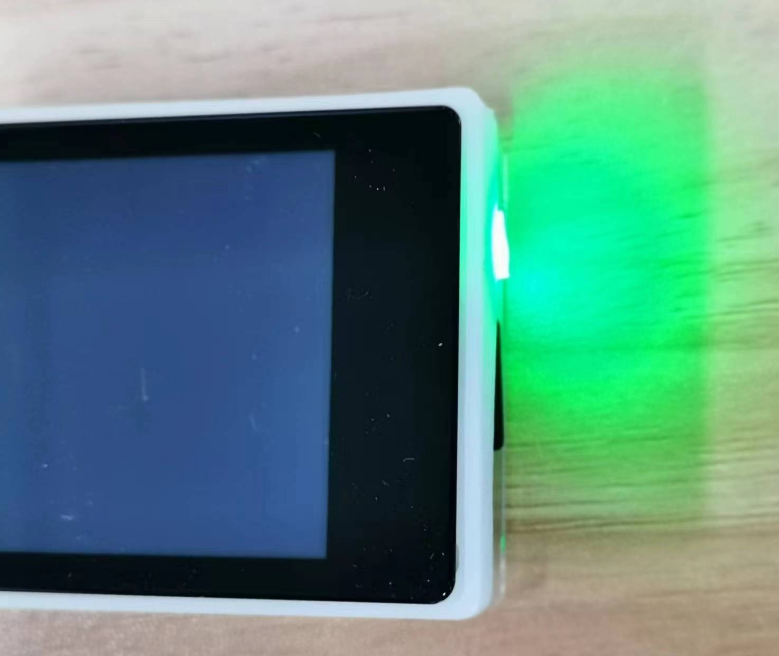
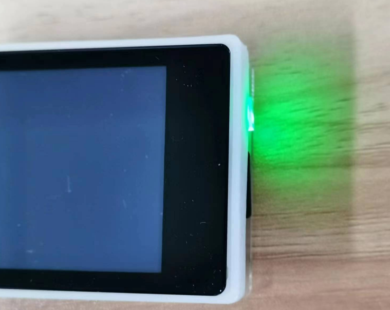
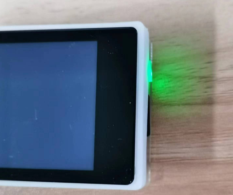
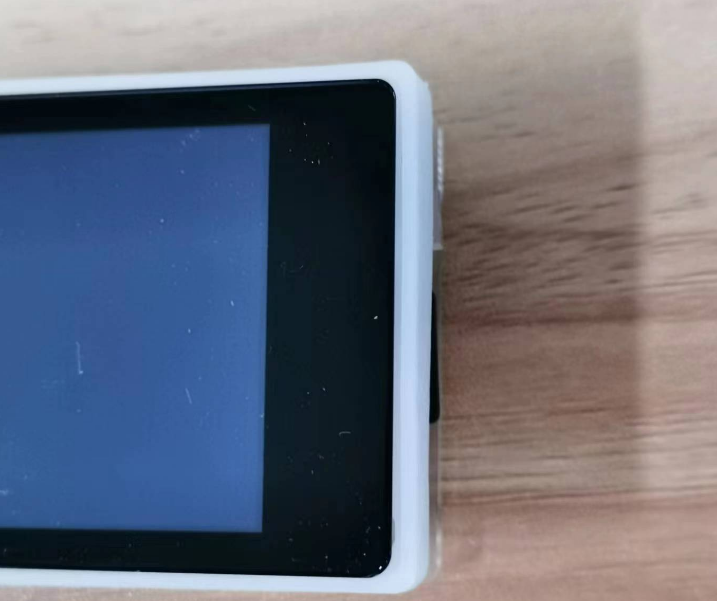
4.3 experimental results
Connect the K210 module to the computer through the microUSB data cable, CanMV IDE click the connect button, after the connection is completed click the Run button to run the routine code. You can also download the code as main.py and run it in the K210 module.
You can see the RGB lights green, and the last from the darkest to the brightest, and then from the brightest to the darkest regulation, rendering breathing light effect.
4.4 the experiments are summarized
Use CanMV IDE, with the factory firmware write a good MicroPython syntax, so that the control of the PWM outputs very easily, by a simple configuration of timer and PWM, and can show a breathing light effect. The PWM output is dependent on the timer, the current K210 a total of 3 timers, each timer has 4 channels, so up to 12 outputs a PWM signal. The PWM duty cycle for output high level with the cycle ratio.