CCD sensor raw data reading
CCD sensor raw data reading1.Experimental Purpose2.Introduction to CCD linear sensors2.1 A simple overview2.2 The working principle of linear CCD3.Experimental wiring4.Experimental phenomena5. experimental result
1.Experimental Purpose
Understand the working principle of CCD and the impact of working environment
2.Introduction to CCD linear sensors
2.1 A simple overview
The model of the CCD sensor for this module is TSL1401, which is a linear sensor composed of a 1x128 photodiode array, related charge amplification circuits, and an internal pixel data retention function. The array consists of 128 pixels, each with a photosensitive area of 3524.3 square micrometers.
2.2 The working principle of linear CCD
The collection timing triggered by this module is shown in the figure:
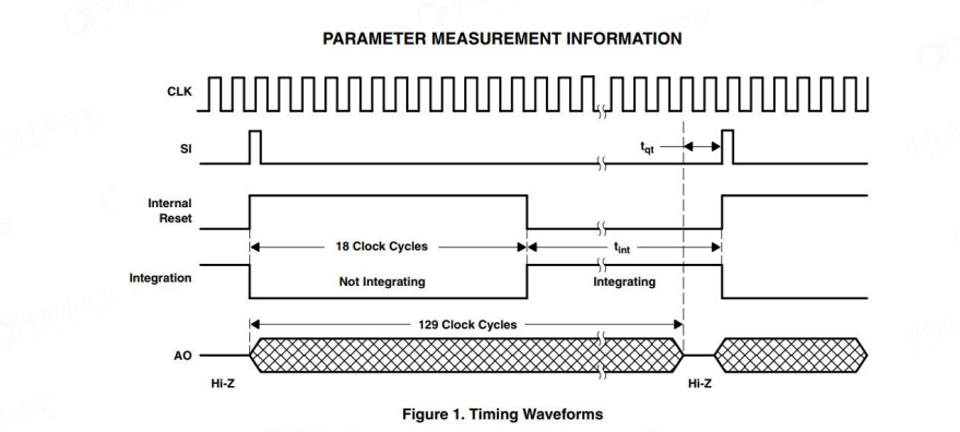
conclusion:
- TSL1401 has one output acquisition cycle every 129 clock cycles, and the clock cycle is provided by the CLK pin.
- When the SI pin receives a high-level signal, the TSL1401 grayscale value acquisition task and grayscale value output task start simultaneously.
- CCD grayscale value collection task: Perform reset work within the 1st to 18th clock cycle (corresponding to the Internal Reset timing in the figure), conduct environmental sensitization within the 19th to 129th clock cycle (corresponding to the Integration timing in the figure), and convert it into electrical signals. The brighter the environment, the stronger the electrical signal. At the same time, if the clock cycle is longer, the sensitivity time is longer and the electrical signal is stronger. The signals collected in the current collection cycle are only allowed to be read in the next cycle.
- CCD grayscale output task: During the 2nd to 129th week, each falling edge of the AO pin outputs a grayscale value, representing the grayscale values of the 1st to 128th pixels from the left. The size of its value can be read through the microcontroller ADC. Similarly, the signal output in the current output cycle belongs to the signal collected in the previous cycle.
3.Experimental wiring
1.The wiring of F103C8T6/RCT6 and linear CCD module is as follows
| STM32/GD32 | CCD |
|---|---|
| PA3 | CLK |
| PA4 | SI |
| PA5 | AO |
| VCC | VCC |
| GND | GND |
2.F103C8T6/RCT6 and serial port wiring are as follows
| STM32/GD32 | USB-TTL |
|---|---|
| PA9 | RXD |
| PA10 | TXD |
| GND | GND |
If it's enough to buy our black STM32 and GD32, you don't need to use TTL modules, just use a type-c data cable
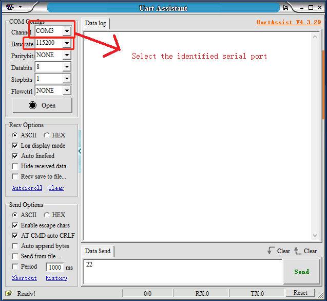
The configuration of the serial assistant is
4.Experimental phenomena
The content output by the serial assistant can be seen, outputting 128 data at a time.
The source code of this tutorial is relatively simple and will not be interpreted. Interested friends can learn it on their own.
5. experimental result
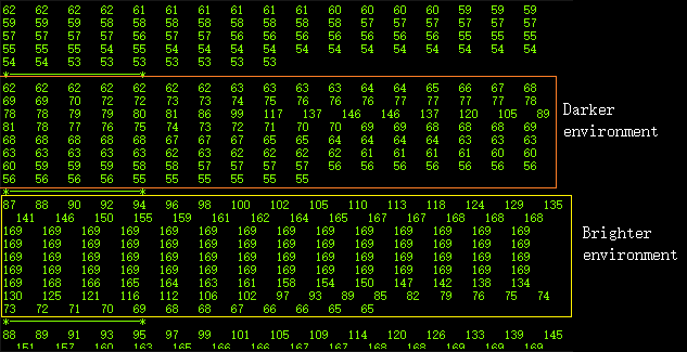
Placing the sensor on the same white paper and changing the brightness of different lighting can result in significant differences in the results obtained.
As shown in the following figure:
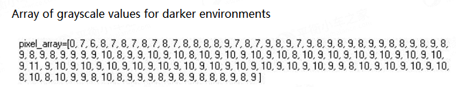
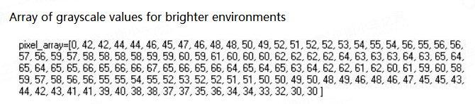 From this, it can be seen that the sensor is highly affected by environmental conditions, and it cannot function properly in environments that are too dark or too bright (usually normal indoor light can operate).