Algorithm processed data
Algorithm processed data1.Experimental Purpose2.Introduction of algorithms2.1 What is an algorithm2.2 Dynamic threshold algorithm2.2.1 brief introduction2.2.3 principle2.2.4 example2.2.5 Source code analysis of algorithms combined with sensors3.Wiring diagram4.experimental result
1.Experimental Purpose
Through the previous experiment, it was found that the operation of the linear CCD module is severely affected by the working environment. This experiment uses a dynamic threshold algorithm to ensure that the CCD module is not affected by the working environment. It is normal to judge whether the CCD lens is facing the centerline position and display it on the LCD or OLED screen
2.Introduction of algorithms
2.1 What is an algorithm
According to Baidu Baike, algorithm refers to an accurate and complete description of the solution scheme, a series of clear instructions to solve problems, and algorithm represents a systematic method to describe the strategy and mechanism of solving problems. That is to say, it is possible to obtain the required output within a limited time for a certain standard input.
CSDN refers to a well-defined calculation process that takes one or a set of values as input and produces one or a set of values as output. Simply put, an algorithm is a series of computational steps used to convert input data into output results.
Simply put, it means turning a problem into a mathematical problem, obtaining one or more formulas from the problem, and then using these formulas to obtain the correct output for the input data.
2.2 Dynamic threshold algorithm
2.2.1 brief introduction
According to the data collected by linear CCD, the sensor is highly affected by environmental light.
Therefore, we need to introduce a dynamic threshold algorithm for sampling data processing, which cuts the collected data to obtain the effective data.
2.2.3 principle
When there are some situations in the image such as shadows, uneven illumination, different contrasts, sudden noise, background grayscale changes, etc., if only a fixed global threshold is used to segment the entire image, the segmentation effect will be affected due to the inability to take into account the various situations in the image. One solution is to segment each part of the image separately using a set of thresholds related to the pixel position (i.e., the threshold is a function of coordinates). This coordinate related threshold is also known as dynamic threshold, and this method is also known as change threshold method or adaptive threshold method. This type of algorithm has a relatively large temporal and spatial complexity, but strong noise resistance, and has good results for images that are difficult to segment using global thresholds.
2.2.4 example
For example, an original image with uneven illumination (bright on the left and dark on the right): If only one global threshold is selected for segmentation, the following two situations will occur, and satisfactory results cannot be obtained. (If the threshold is low and the effect on bright areas is good, then the dark areas are poor) (If the threshold is high and the effect on dark areas is good, then the bright areas are poor) If local thresholds are used, different thresholds can be selected in the bright and dark areas respectively, making the overall segmentation effect more rational. (The segmentation result of taking local thresholds based on two regions) Furthermore, if each number uses a different local threshold, a more ideal segmentation effect can be achieved.
2.2.5 Source code analysis of algorithms combined with sensors
void Find_CCD_Zhongzhi(void){ static u8 i,j,Left,Right,Last_CCD_Zhongzhi; static u16 value1_max,value1_min; value1_max=ADV[0]; //Dynamic threshold algorithm, reading maximum and minimum values for(i=5;i<123;i++) //Remove 5 points on each side { if(value1_max<=ADV[i]) value1_max=ADV[i]; } value1_min=ADV[0]; for(i=5;i<123;i++) { if(value1_min>=ADV[i]) value1_min=ADV[i]; } CCD_Yuzhi=(value1_max+value1_min)/2; //Calculate the threshold for this centerline extraction for(i = 5;i<118; i++) //Find the left jump edge { if(ADV[i]>CCD_Yuzhi&&ADV[i+1]>CCD_Yuzhi&&ADV[i+2]>CCD_Yuzhi&&ADV[i+3]<CCD_Yuzhi&&ADV[i+4]<CCD_Yuzhi&&ADV[i+5]<CCD_Yuzhi) { Left=i; break; } } for(j = 118;j>5; j--)//Find the right jump edge { if(ADV[j]<CCD_Yuzhi&&ADV[j+1]<CCD_Yuzhi&&ADV[j+2]<CCD_Yuzhi&&ADV[j+3]>CCD_Yuzhi&&ADV[j+4]>CCD_Yuzhi&&ADV[j+5]>CCD_Yuzhi) { Right=j; break; } } CCD_Zhongzhi=(Right+Left)/2;//Calculate centerline position if(myabs(CCD_Zhongzhi-Last_CCD_Zhongzhi)>70) //Calculate the deviation of the centerline, if it is too large CCD_Zhongzhi=Last_CCD_Zhongzhi; //Then take the previous value Last_CCD_Zhongzhi=CCD_Zhongzhi; //Save Last Deviation} - CCD_Yuzhi:Extract the threshold of the centerline collected this time
- Through this CCD_ Yuzhi threshold to determine the position of the black line in the collected data this time
- Find the left jump edge and the right jump edge, and the middle segment between them is the position of the black line, as shown in the following figure.
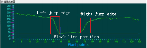
- According to the black line in this section, the middle position value is the point where the center point of the sensor faces the black line, which is the CCD_ Zhongzhi, this value
- CCD_Zhongzhi = 64 That means the center point of the sensor is facing the black line
- CCD_Zhongzhi > 64 This means that the center point of the sensor is leaning to one side (to the right) towards the black line
- CCD_Zhongzhi < 64 This means that the center point of the sensor is leaning to one side (to the left) towards the black line
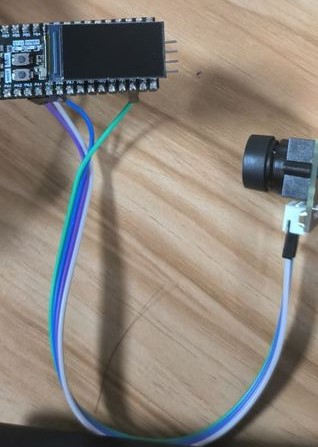
3.Wiring diagram
1.Wiring of STM32 and CCD module
| STM32/GD32 | CCD |
|---|---|
| PA4 | SI |
| PA3 | CLK |
| PA5 | AO |
2.STM32/GD32 and screen wiring (choose one of the following two options)
- Using STM32/GD32 and OLED screen wiring (OLED screen needs to be purchased separately)
| STM32/GD32 | OLED |
|---|---|
| PB10 | SCL |
| PB11 | SDA |
| VCC | VCC |
| GND | GND |
2.Using STM32/GD32 and LCD screen wiring (LCD screen needs to be purchased separately)
| STM32C8T6/GD32C8T6 | LCD |
|---|---|
| PB10 | SCLK |
| PB11 | MOSI |
| PA7 | RES |
| PB0 | DC |
| PB1 | CS |
| PA6 | BLK |
 |
| STM32RCT6 | LCD |
|---|---|
| PB8 | SCLK |
| PB9 | MOSI |
| PC11 | RES |
| PC12 | DC |
| PD2 | CS |
| PC10 | BLK |
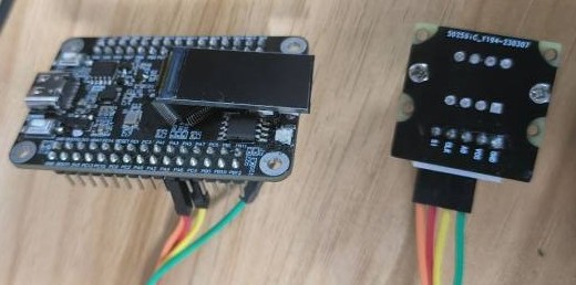 |
If you directly purchase our black STM32/GD32, you can directly connect the LCD screen to the LCD screen interface on the board without using DuPont cables
4.experimental result
After burning the normal code, it can be observed that the OLED screen/LCD screen has the following display, and the following figure shows the display effect of the OLED screen
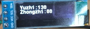
Yuzhi:Dynamic threshold Zhongzhi:mid-value
By shifting the lens, it can be seen that the median is changing
It is best to experiment in an environment with only black and white lines for the best results.