Assembly and wiring of stm32 car
Assembly and wiring of stm32 car1.Experiment preparation2.Car wiring2.1 Stm32 and dual driver board wiring part2.2 Wiring of STM32F103RCT6 and infrared sensor2.3 Wiring of STM32RCT6 and k2103.Follow the line driving3.1 Main source code analysis3.2 Experimental effect
1.Experiment preparation
Material preparation
Smart car mini chassis *1
stm32F103RCT6 *1
Yahboom's dual-channel motor driver board *2 (Other motor driver boards may not be suitable for the source code provided in this tutorial, you need to transplant it yourself)
Four-way tracking module *1
310 motor *4
k210 viewing angle module *1
K210 angle of view module heightened bracket *1
7.4V battery *1
Several DuPont lines
M3 copper pillars, some M3 screws
2.Car wiring
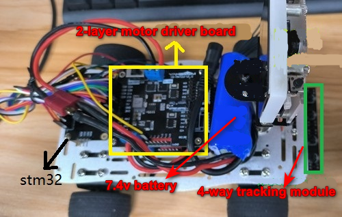
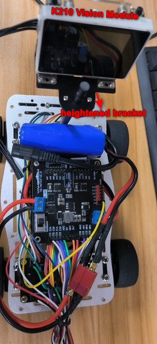
After the car is assembled, as shown in the figure below.
2.1 Stm32 and dual driver board wiring part
Wiring of stm32F103RCT6 and dual motor board (top board)
| STM32RCT6 | The top two-way motor board |
|---|---|
| PA11 | BN1 |
| PA8 | BN2 |
| PC6 | AN1 |
| PC7 | AN2 |
| 3.3 | 3V3 |
| GND | GND |
| PA0 | E2A |
| PA1 | E2B |
| PA15 | E1A |
| PB3 | E1B |
Wiring of stm32F103RCT6 and dual motor board (lowest board)
| STM32RCT6 | The bottom two-way motor board |
|---|---|
| PB0 | BN1 |
| PB1 | BN2 |
| PC8 | AN1 |
| PC9 | AN2 |
| 3.3 | 3V3 |
| GND | GND |
| PA7 | E2A |
| PA6 | E2B |
| PB7 | E1A |
| PB6 | E1B |
The motor drive board on the top layer is the motor of the two wheels (that is, the front motor) that is connected to the electromagnetic sensor.,
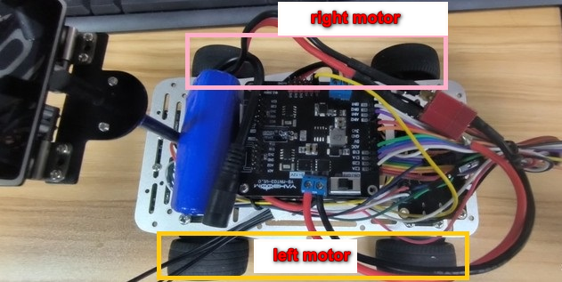
motorA--->right motor、motorB--->left motor
The motor drive board at the bottom is connected to the two-wheeled motors away from the electromagnetic sensor (that is, the motor at the back),
motorA--->right motor、motorB--->left motor
2.2 Wiring of STM32F103RCT6 and infrared sensor
| STM32RCT6 | 4-way line inspection sensor |
|---|---|
| PA5 | S1 |
| PA4 | S2 |
| PA3 | S3 |
| PA2 | S4 |
| 3.3V | VCC |
| GND | GND |
2.3 Wiring of STM32RCT6 and k210
| STM32RCT6 | k210 |
|---|---|
| PA9 | RXD |
| PA10 | TXD |
| VCC | VCC |
| GND | GND |
At this point, the assembly and wiring of the car is over.
3.Follow the line driving
Flash the STM32_K210_AI.hex file in the stm32 source code provided in this tutorial to the assembled car. The car can drive on the black line(To flash the program to the car through the serial port), This series of tutorials only provides the source code of the stm32 car part. If you only need a small part of the functions in it, you can transplant it into the source code.
3.1 Main source code analysis
void Track_line(void) //IR tracking processing Detecting the black line is to turn on the light { if((IN_S1 == 0 || IN_S3 == 0) && IN_S2 == 1 && IN_S4 == 1) //go straight { Motion_Set_Pwm(100,0,100,0);//Upper right wheel, lower right wheel, upper left wheel, lower left wheel } //turn left and right if(IN_S2 == 0 && IN_S3 == 1 ) { //Turn left Motion_Set_Pwm(500,500,-350,-350); } else if(IN_S4 == 0 && IN_S1 == 1 ) { Motion_Set_Pwm(-550,-550,550,550); } if((IN_S1 == 0 && IN_S2 == 0) && (IN_S3 == 0 && IN_S4 == 0))//all black lines { Motion_Set_Pwm(0,0,0,0);//stop //Motion_Set_Pwm(50,0,50,0);//go ahead }}The above is a simple line inspection function. After initializing the 4-way line inspection module and the motor, call this function in the while(1) loop to realize the car line inspection
3.2 Experimental effect
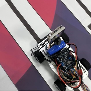
The car will be able to patrol the line normally, and will stop when it hits the stop line.