pico_ K210 color recognition
1.K210 and Pico communication
1.1 Experimental premises
This tutorial uses Pico, and K210 requires running the program in K210-AI (stm32_pico_arduino) to start the experiment Pico * 1 K210 perspective module * 1 (requires SD card (with AI model inside) and camera) USB to TTL module * 1
1.2 Experimental wiring
| pico | USB to TTL module |
|---|---|
| GP8 | RXD |
| GND | GND |
| pico | k210 |
|---|---|
| GP9 | TXD |
| GND | GND |
| VCC | 5V |
| Wiring as shown in the diagram: |


1.3 Main code parsing
xu1 = UART(1, baudrate=115200, tx=Pin(8), rx=Pin(9), bits=8, parity=None, stop=0)
k210_data_class = 0 k210_data_x = 0 k210_data_y = 0 k210_data_w = 0 k210_data_h = 0 k210_data_id = 0 k210_data_msg = ""
while True: while u1.any() >0: rxx=u1.read() recv_k210_data(rxx) if k210_data_class != 0: if k210_data_class == 1: sstr = "x="+str(k210_data_x) +" y="+str(k210_data_y) +" w="+str(k210_data_w) +" h="+str(k210_data_h) +"\r\n" u1.write(sstr) #u1.write(k210_data_msg+'\r\n') k210_data_class = 0Obtained from the program
- k210_data_class :Routine number
- k210_data_x :It identifies the horizontal coordinate of the upper left corner of the box (range: 0-240)
- k210_data_y :It identifies the vertical coordinate of the upper left corner of the box (range: 0-320)
- k210_data_w :The width of the recognized box (range: 0-240)
- k210_data_h :The length of the recognized box (range: 0-320)
- k210_data_id :It's a recognized label
- k210_data_msg :It's the identified information
This processing mainly involves receiving a message from k210 and calling recv_ K210_ Data() for processing and assigning the processed information to k210_ Data_ Members of XXX. Attention If you want to develop for the second time, without changing the K210 program and data processing functions, directly call K210_ Data_ The variable of XXX is good (xxx: refers to x y w h id msg)
1.4 experimental phenomena
- After connecting the cable, the K210 perspective module runs offline. Please check 【6.2 K210 as coprocessor】--【ReadMe】
- Set the serial port assistant to the interface shown in the figure
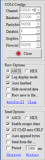
- Download Pico's Python firmware into Pico and run the color recognition program provided in this tutorial. How to run Pico's Python program? Please refer to the Pico related environment building tutorial, which will not be elaborated in this tutorial
- Then k210 runs the relevant routines, and the serial assistant will print out the important information transmitted by k210 to Pico. The phenomenon shown in the following figure is the result of color recognition
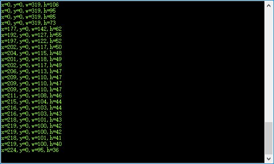 This routine only outputs data for these four members of x\y\w\h