1. MoveIt configuration
1. MoveIt configuration1.1.Start the program1.2. Configuration process1.2.1. Load URDF model1.2.2. Create collision exemption matrix1.2.3. Create a motion planning group1.2.3.1. Add robotic arm planning group1.2.3.2. Add gripper planning group1.2.4. Create preset poses (Robot Poses)1.2.5. Set end influence joints1.2.6. Create ROS controller1.2.7. Add author information. If you don’t add it, it will not be generated.1.2.8. Generate configuration file1.3. Detailed explanation of MoveIt configuration package1.3.1、config folder1.3.2. launch folder1.4. Configuration verification
1.1.Start the program
Start the roscore
roscore
Start the MoveIT
xxxxxxxxxxrosrun moveit_setup_assistant moveit_setup_assistant
1.2. Configuration process
1.2.1. Load URDF model
If an error [model not found] is reported when loading the model, exit MoveIt-->enter the workspace-->compile (sudo apt update)-->update the environment (source devel/setup.bash)-->start the MoveIt configuration again . The interface after startup is as follows:
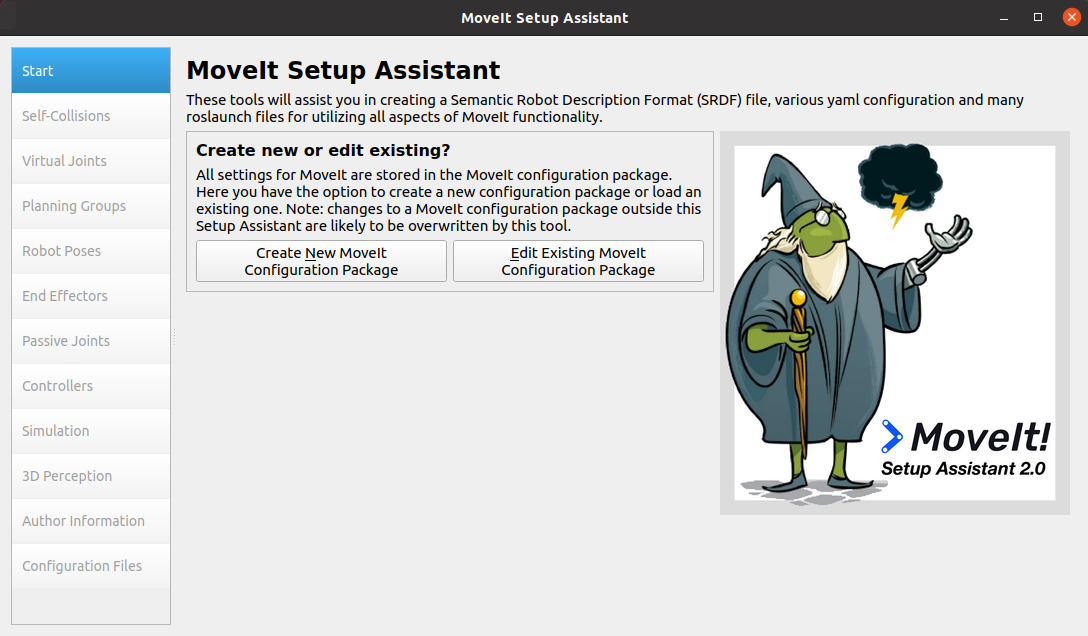
If you are loading the model generation configuration for the first time, click [Create New MoveIt Configuration Package]; if you are modifying the generated configuration file, click [Edit Existing MoveIt Configuration Package].
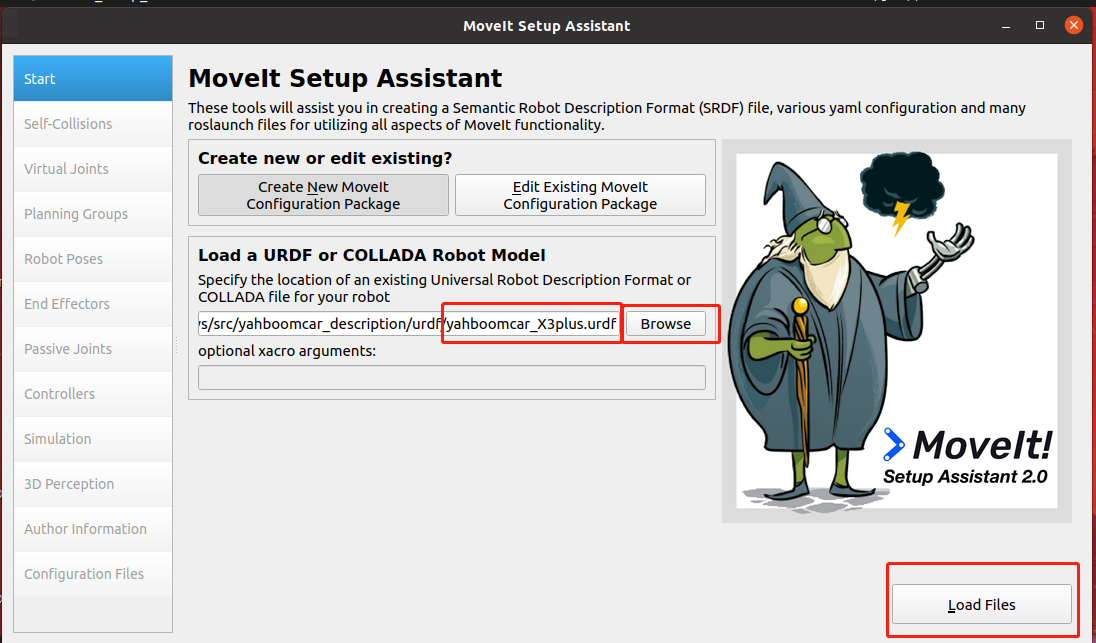
Click the [Browse] button, find the URDF model file, and click [Load Files] in the lower right corner to load it.
1.2.2. Create collision exemption matrix
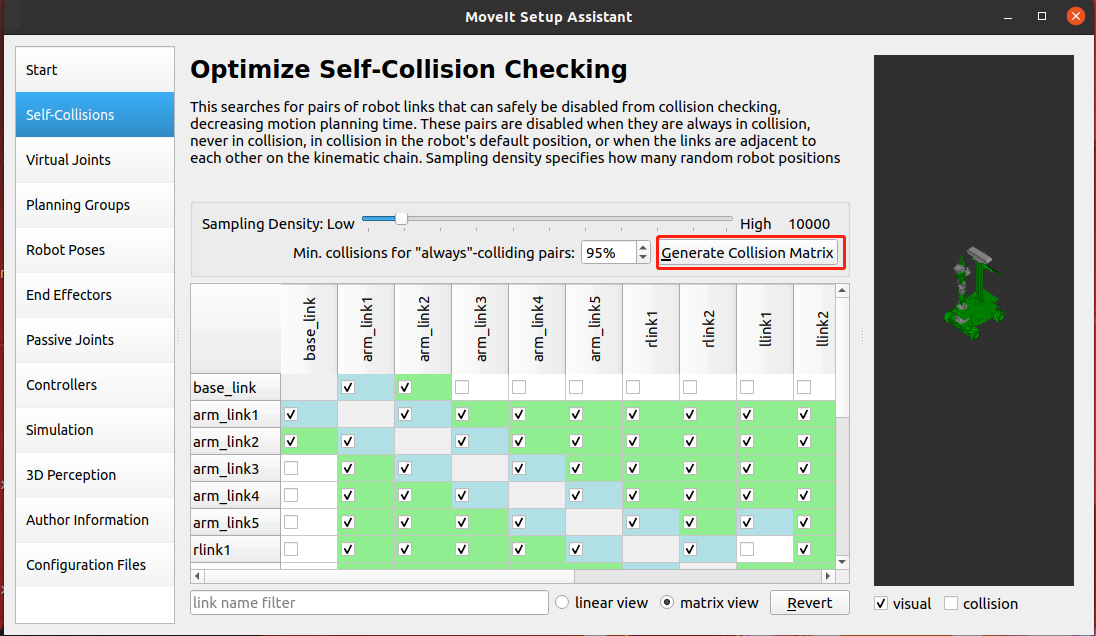
Collision detection is a very complex computational process. For multi-joint robotic arms or humanoid robots, the mechanical structure is complex and there are many joints, and collision detection requires a lot of spatial geometry calculations. But for rigid-body robots, collisions between some joints are impossible, such as adjacent limbs. The purpose of generating self-collision here is to tell us which joints will not collide with each other. In the subsequent collision detection algorithm, the detection between these joints can be directly skipped to improve detection efficiency.
After the model is loaded, select [Self-Collisions] and click the [Generate Collision Matrix] button.
1.2.3. Create a motion planning group
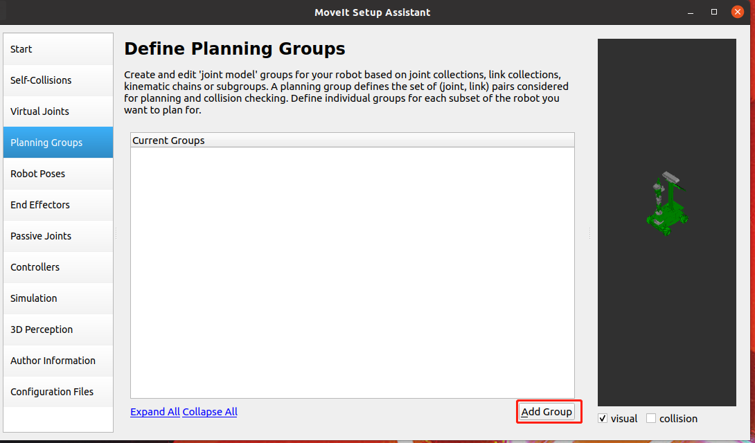
Planning Group is one of the core parts of MoveIt. Click [Add Group] to add a planning group
1.2.3.1. Add robotic arm planning group
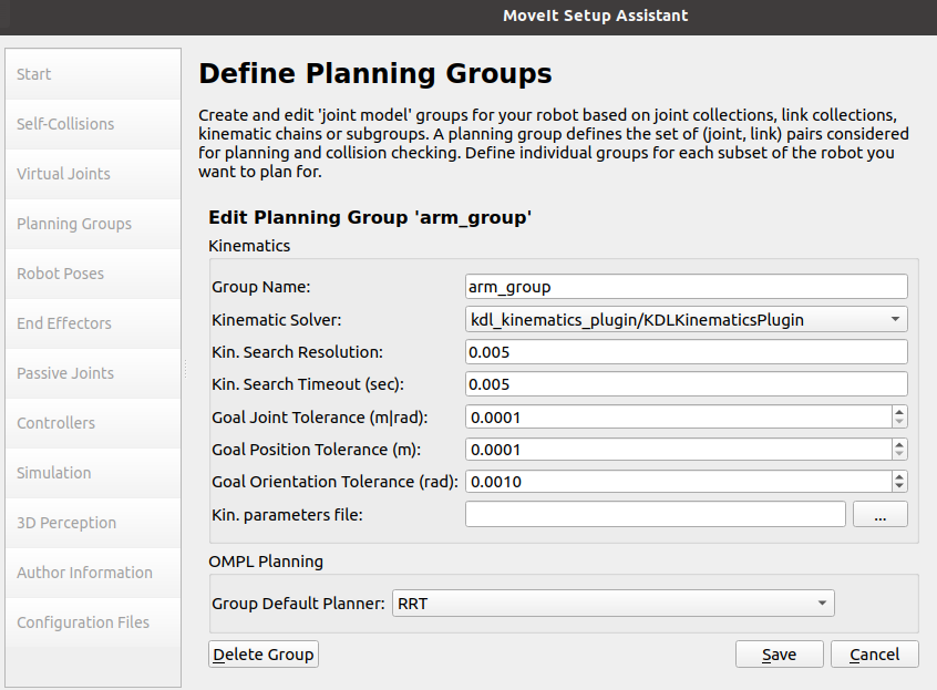
Group Name:Create a group name and set it to [arm_group].
Kinematic Solver: Here we choose [kdl]
Kinematics solving tool, this is responsible for solving forward kinematics (Forward Kinematics) and inverse kinematics (IK). Generally we choose KDL, The Kinematics and Dynamics Library. This is a kinematics and dynamics library that can well solve the forward and inverse kinematics problems of single-chain mechanical structures with more than 6 degrees of freedom.
Of course, you can also use other IK Solver, such as SRV or IK_FAST, or you can even develop a new Solver yourself and insert it.
Kin. Search Resolution: Sampling density of joint space
Kin. Search TImeout: Solving time. If the equipment performance is insufficient or there is no solution within the specified time in the actual application process, the time can be increased; for example, set to [0.1], [0.01].
Group Default Planner:You can choose RRT or None.
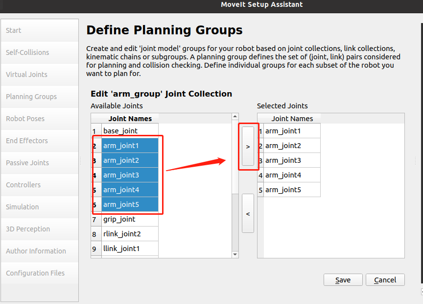
Click [Add Joints] to add joints.
Select arm_joint1 to arm_joint5, and then click >, as shown in the figure below,
Click save to complete adding the robotic arm group, as shown in the figure below.
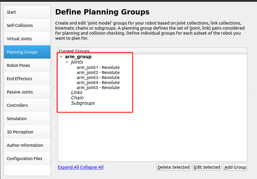
Double-click arm_group to view,
1.2.3.2. Add gripper planning group
Click [Add Group] to add a gripper planning group.
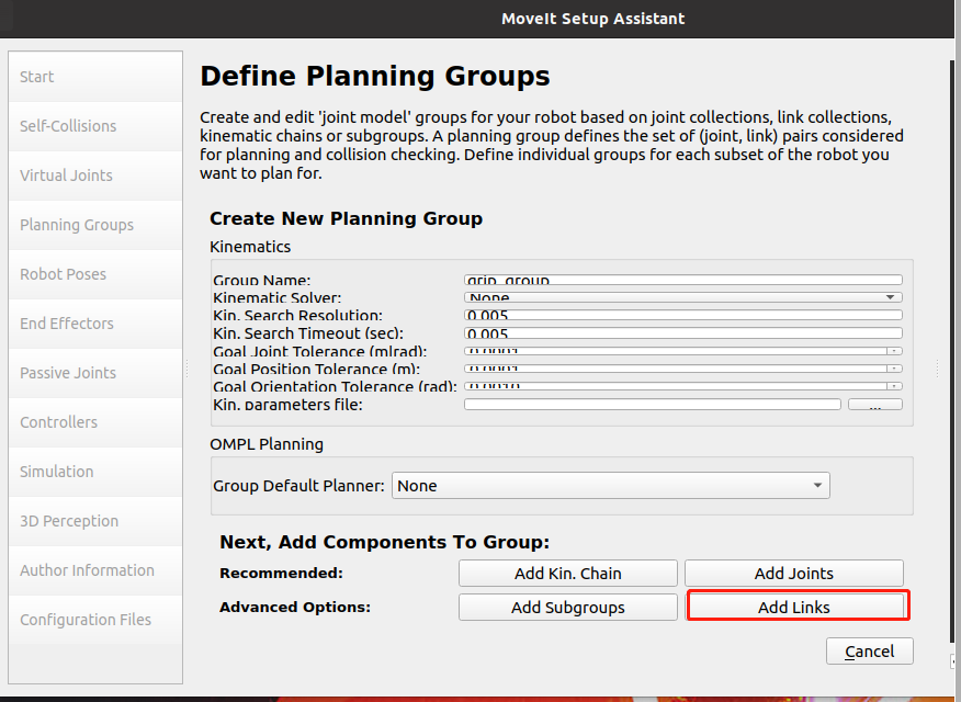
Create a group name and set it to [grip_group]. There is no need to set up a kinematic solver; click [Add Links] to add the gripper link.
Select the connecting rod of the clamping jaw part, click [>], the right side will be added automatically, and click [Save] to save.
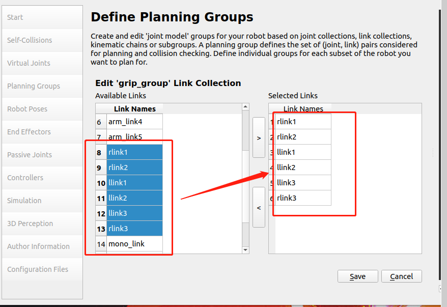
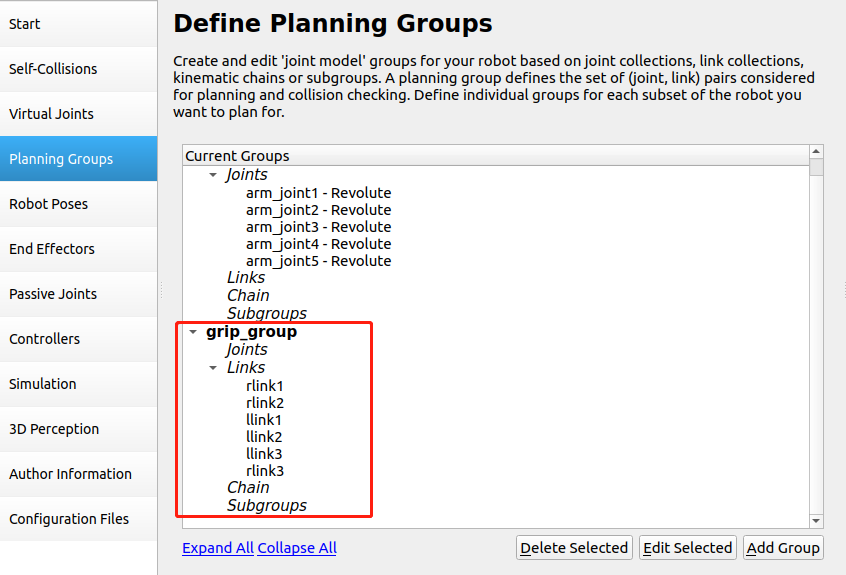
The settings are as shown in the picture below,
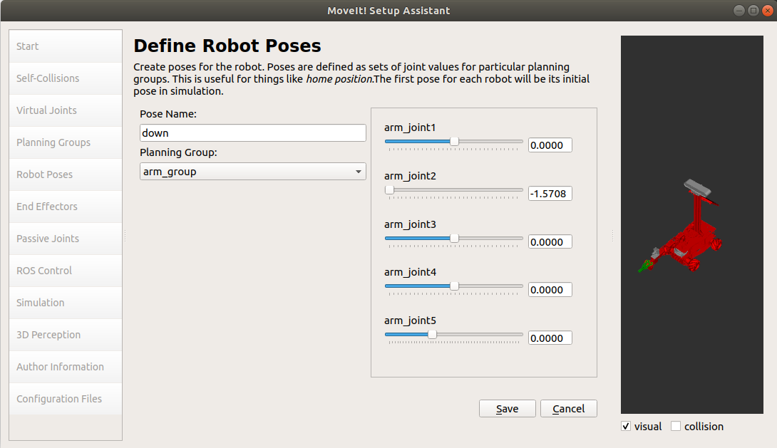
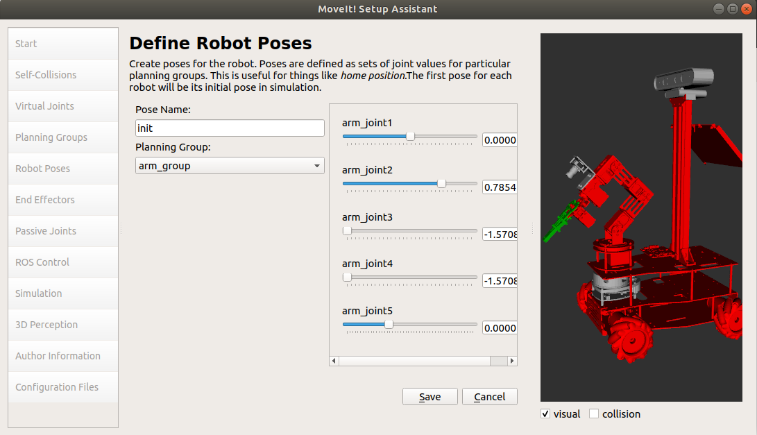
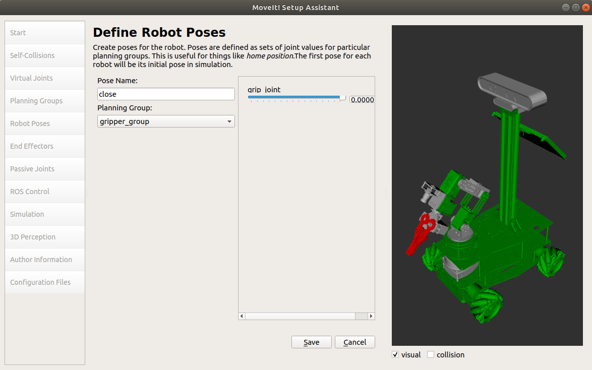
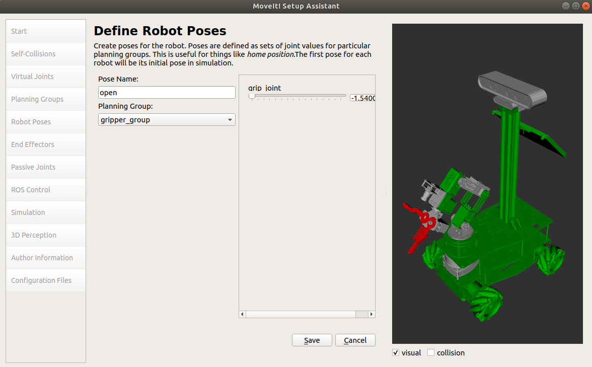
1.2.4. Create preset poses (Robot Poses)
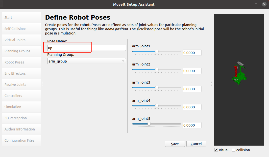
Select [Robot Poses] and click [Add pose] to add a pose.
Add the robot arm posture, and set the posture name Pose Name to [up]
Add [down] gesture
Add [init] gesture
Add the gripper [close] posture
Add the gripper [open] posture
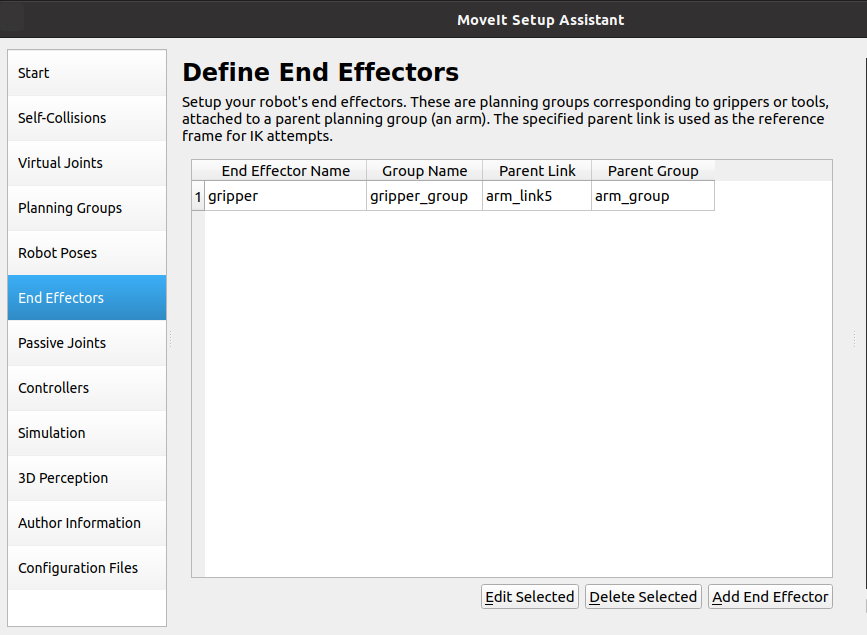
1.2.5. Set end influence joints
Select [End Effectors] and set as shown below
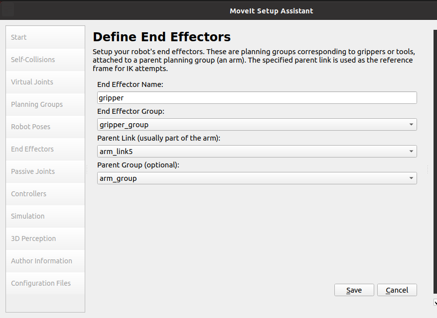
Click Save to save and exit. The settings are completed as shown in the figure below.
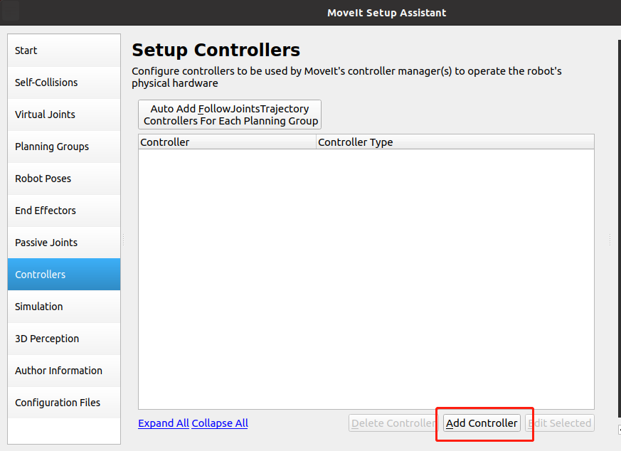
1.2.6. Create ROS controller
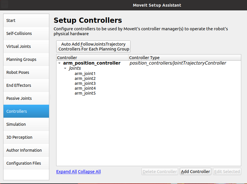
Select [Controllers], click Add Controller,
Then,Controller Name:arm_position_controller,Controller Type choose position_controllers/JointTrajectoryController
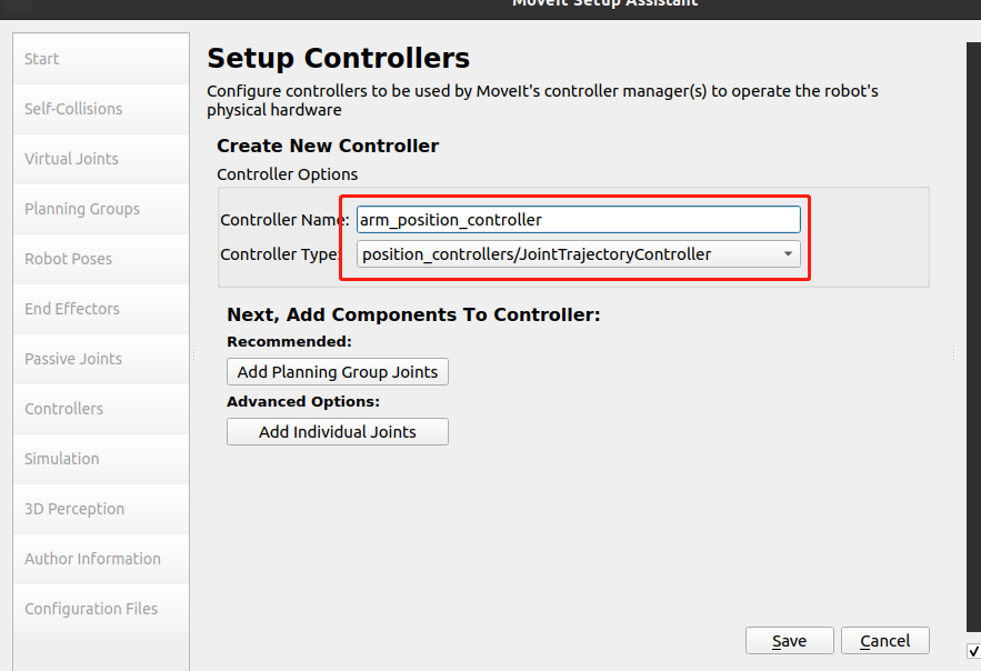
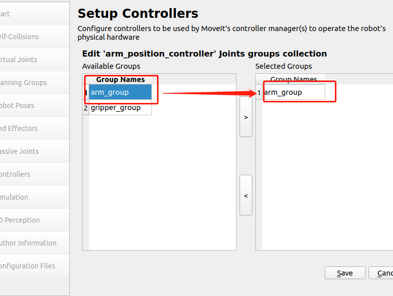
Click Add Planning Group Joints, select arm_group, click >, and click save to save.
The final configuration is shown in the figure below,
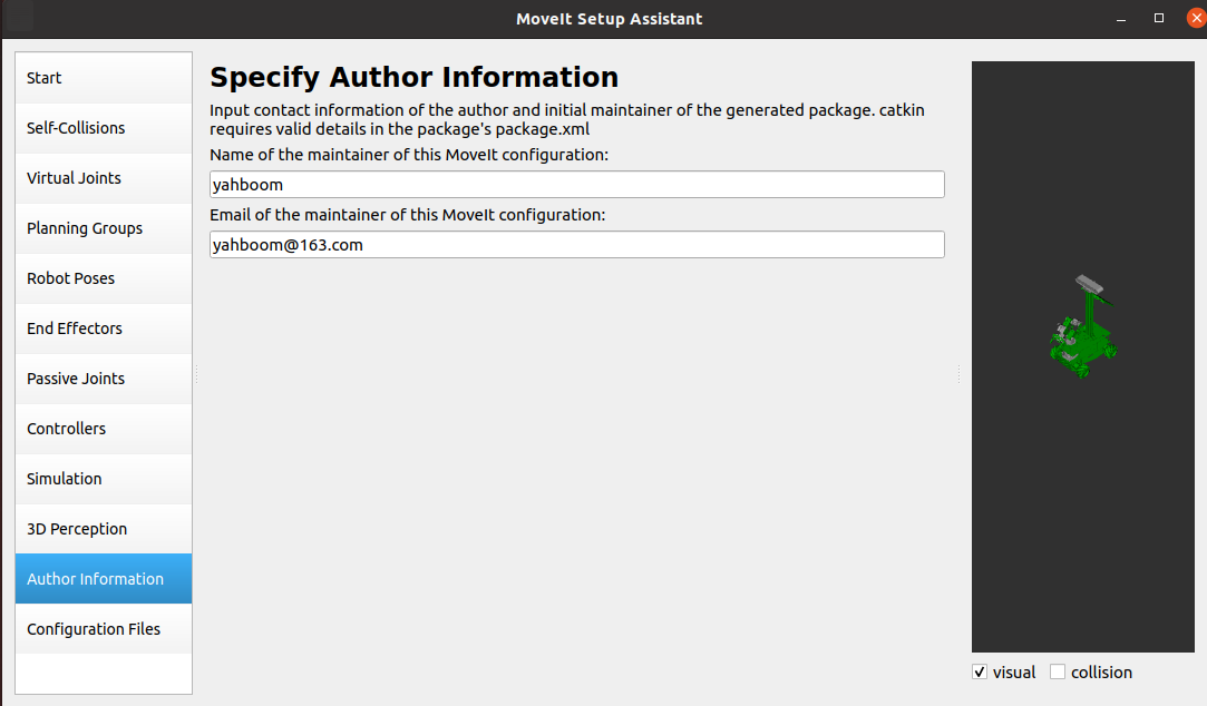
1.2.7. Add author information. If you don’t add it, it will not be generated.
Select [Author Information] and add the following content.
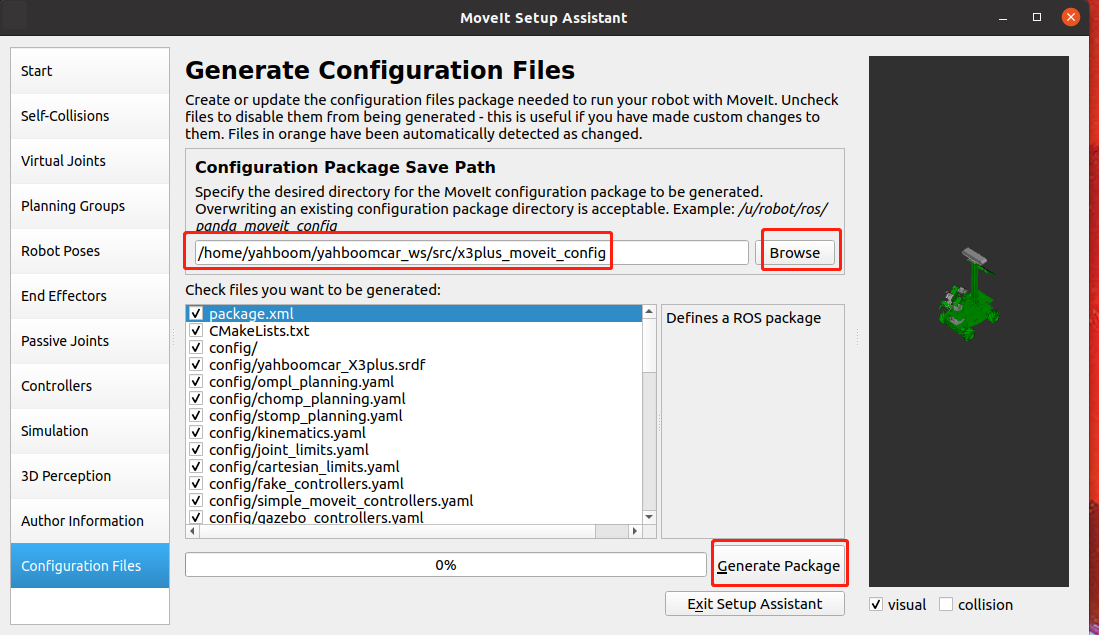
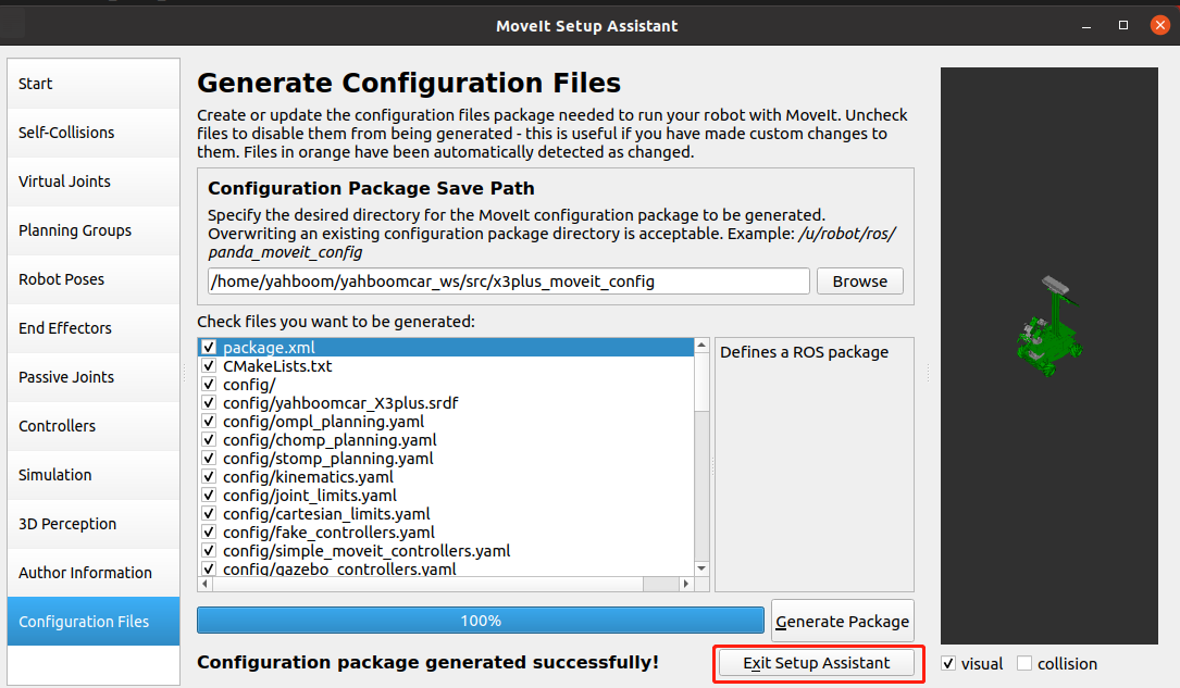
1.2.8. Generate configuration file
Select [Configuration Files], click [Browse], select the [x3plus_moveit_config] folder (the folder must be empty), and click the [Generate Package] button to generate the configuration file. After completion, click [Exit Setup Assistant].
After the generation is completed, click Exit Setup Assistant to exit the configuration.
1.3. Detailed explanation of MoveIt configuration package
Open the [x3plus_moveit_config] folder we just created, and we find that there are two folders: config and launch.
1.3.1、config folder
- fake_controllers.yaml:This is a virtual controller configuration file that allows us to run MoveIt without a physical robot or even any simulator (such as gazebo) opened.
- joint_limits.yaml:This records the position, velocity and acceleration limits of each joint of the robot, which will be used in future planning.
- kinematics.yaml:Something set by the motion planning group, used to initialize the kinematics solution library
- yahboomcar_X3plus.srdf:This is an important MoveIt configuration file.
- ompl_planning.yaml:Here are various parameters for configuring various OMPL algorithms.
- SRDF file: SRDF is the configuration file of moveit, used in conjunction with URDF. We can see that this is a configuration file in xml format. The root is robot and has an attribute name='yahboomcar_X3plus'. The following is what was just set up in the Setup Assistant, including the definition of groups, poses, terminal controllers, virtual joints, and collision-free matrix ACM. Theoretically, as long as we have srdf and urdf, we can completely define a robot moveit information.
1.3.2. launch folder
- demo.launch:demo is the summary point of the run. When we open it, we can see that it includes other launch files.
- move_group.launch:As the name suggests, the function of move group is to make a planning group move. The default is to use the ompl motion planning library. Others are to set some basic parameters and can be skipped for now.
- planning_context.launch:Here we can see that the urdf and srdf files used are defined, as well as the kinematics solution library. It is not recommended to change these manually, but if you need to use a different urdf, srdf, you can change it here.
- setup_assistant.launch:If you need to change some configuration, you can run it directly.
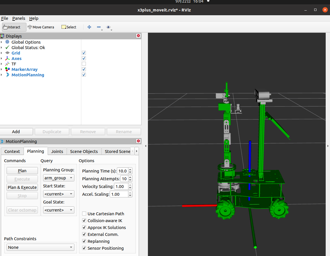
1.4. Configuration verification
Enter the workspace where the configuration file is located and execute the following command
xxxxxxxxxxcd ~/yahboomcar_ws # Enter the work spacecatkin_make # Compilingsource devel/setup.bash # Update system environmentroslaunch arm_moveit_demo x3plus_moveit_demo.launch sim:=true # Start up moveITExamples are as follows