Introduction to expansion board
The Dofbot-SE expansion board is compatible with a variety of master control boards. Only one master control can be used to connect to the expansion board at a time.
It supports Raspberry Pi, Jetson Nano, STM32, Arduino UNO, micro:bit, STC51, and even There is also an external I2C interface reserved to support other main control boards with I2C functions.
Introductions of components location and function on expansion board
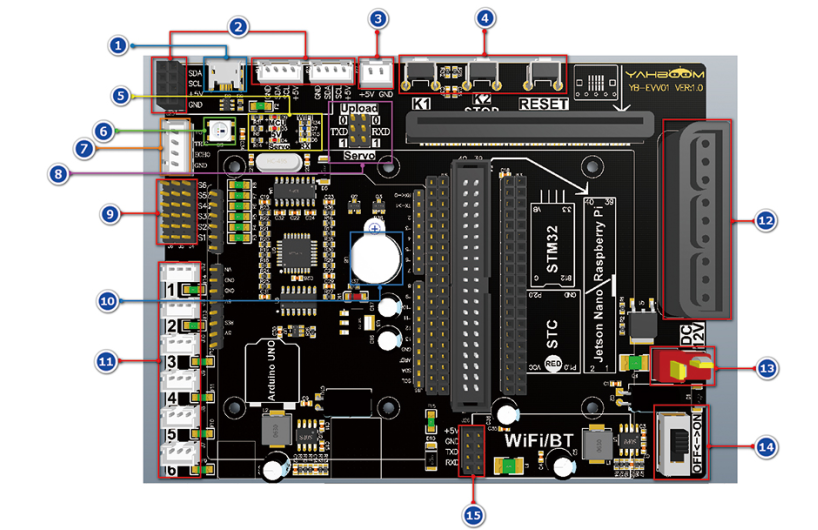
- Micro USB interface: it can be used to download programs for Arduino UNO, STM32, STC51, or update the firmware of the bottom MCU, and communicate with the main control board by serial port.
- 12C interface: it can be used to connect l2C device.
- Cooling fan interface: It is used to connect with cooling fan, not to supply power to other devices.
- Buttons:
*K1 button*: In the default mode, press the K1 button once to reset the bus servo, and the DOFBOT keeps upright. Double-click the K1 button to reset the servo quickly. In the study mode, press the K1 button to learn an action. Raspberry Pi and Jetson Nano version in the WiFi configuration mode, long press for 5s to make camera scan the QR code to connect to WiFi.
*K2 button*: Short press is the emergency stop function of the bus servo to turn off the torque of the bus servo; long press for about 10 seconds is to turn off and turn on the BootLoader function of the underlying single-chip microcomputer. After the BootLoader function is turned on, the RGB light shows a marquee effect.
*RESET key*: The reset function of the coprocessor (STM8), STM32 and Arduino UNO.
- Status indicator:
*Red light be marked with MCU:* It is the status indicator of the coprocessor (STM8). When the coprocessor (STM8) is running normally, the red light flashes twice every 3 seconds.
*Red light be marked with 5V*: 5V voltage indicator of the expansion board.
*Red light be marked with Servo*: It is servo power supply indicator, keeping on when servo work normally.
*Blue light be marked with WiFi*: It keeps on after connecting to WiFi (just for factory program is started).
*Yellow light be marked with RX*: When micro USB port receiving data, it will flash.
6.RGB lights: RGB lights controlled by coprocessor (STM8). The main board can send commands to coprocessor (STM8) to make the RGB lights light up in different colors.
- Ultrasonic interface: It can be connected to ultrasonic module.
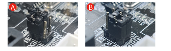
- Coprocessor (STM8) serial port function selection: In the default state, connect both TXD and RXD to 1 (Servo) by jumper cap, coprocessor can control the bus servo (as shown in Figure A above). If you connect both TXD and RXD to 0 (Upload) by jumper caps, you can update the firmware of coprocessor (STM8)through the micro USB interface (as shown in Figure B above).
- PWM servo interface: It can be used to connect PWM servo.
- Buzzer: Active buzzer, controlled by coprocessor (STM8).
- Bus servo interface: It can be used to connect bus servo. If multiple servos are cascaded, each port can connect up to 6 servos.
- PS2 handle receiver socket: Plug in the PS2 handle receiver.
- T-type power supply interface: DC12V power supply interface.
- Power switch: Power switch of DOFBOT.
- Serial port: it can be used to connect WiFi or Bluetooth module.
The installation position of the main control board
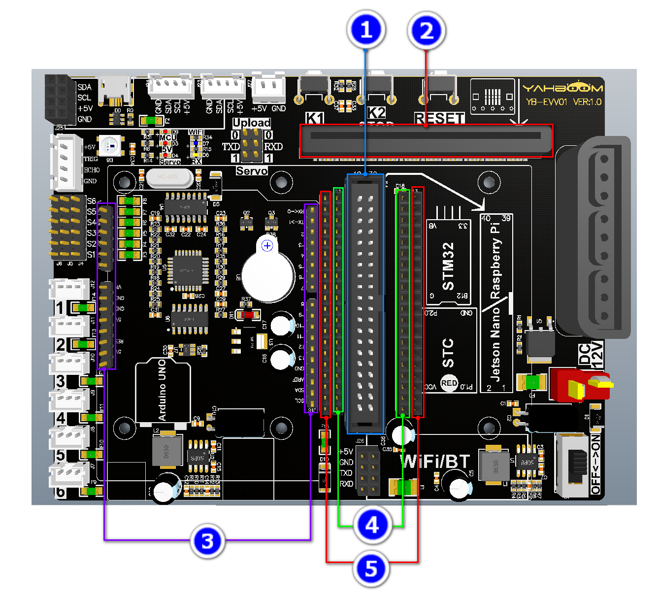
- Raspberry Pi and Jetson Nano board installation location
- Microbit installation location
- Arduino UNO installation location
- STM32 core board installation location
- STC51 core board installation location