Drive motor
Drive motor1. Experimental purpose2. Hardware connection3. Core code analysis4. Compile, download and flash firmware5. Experimental results
1. Experimental purpose
Use the PWM output of the microROS control board to learn how the ESP32 controls the motor.
2. Hardware connection
As shown in the figure below, the microROS control board integrates four encoder motor control interfaces. An additional encoder motor needs to be connected. The motor control interface supports 310 motors. A type-C data cable also needs to be connected to the computer and the microROS control board to burn firmware. Function.
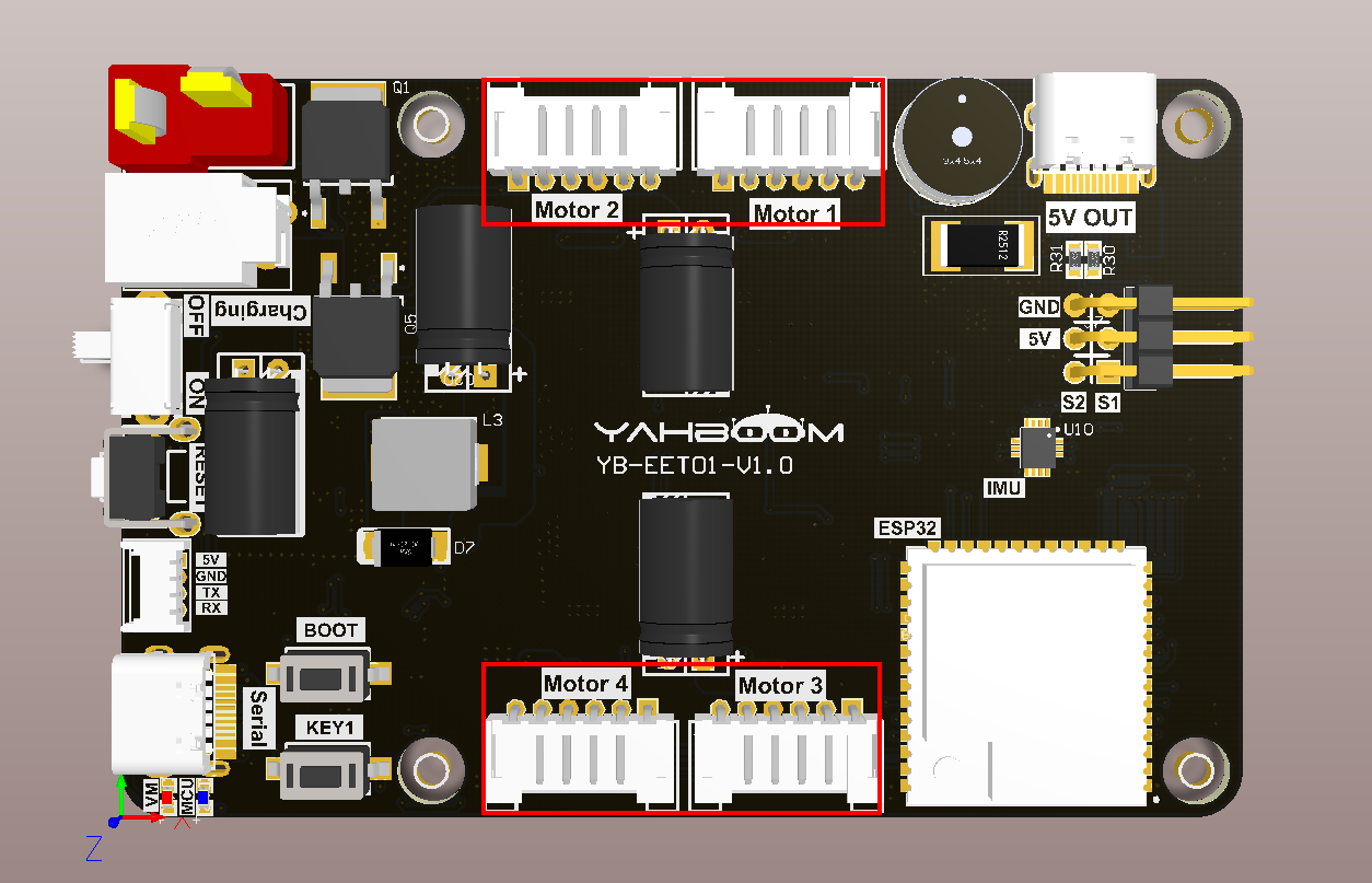
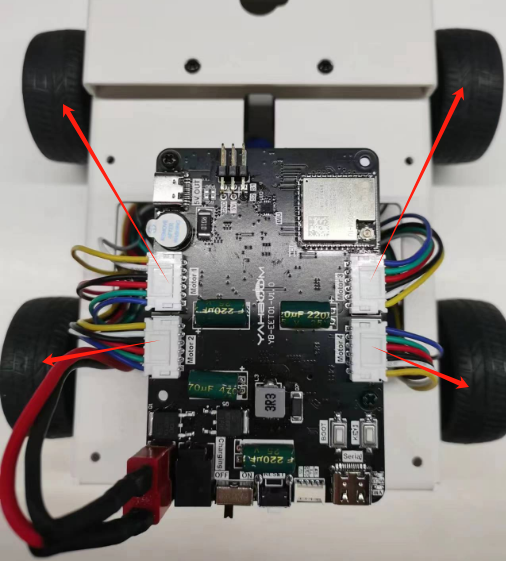
The corresponding names of the four motor interfaces are: left front wheel->Motor1, left rear wheel->Motor2, right front wheel->Motor3, right rear wheel->Motor4.
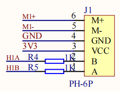
Motor interface line sequence, there is a detailed line sequence silk screen on the back of the microROS control board. Here we take Motor1 as an example. M1+ and M1- are the interfaces for controlling the rotation of the motor. GND and VCC are the power supply circuits of the encoder. H1A and H1B are the encoder pulses. Detection pin.
Note: If you are using the 310 motor and motor cable provided by Yabo Intelligence, connect the white wire shell end to the interface on the microROS control board, and the black wire shell end to the 310 motor interface.
3. Core code analysis
The virtual machine path corresponding to the program source code is as follows
~/esp/Samples/esp32_samples/pwm_motor
Before starting to write code, you need to import the bdc_motor component from the ESP32 library, create a new idf_component.yml file in the pwm_motor component, and then add the following content to import the bdc_motor component dependency.
xxxxxxxxxxdependencies:bdc_motor: "^0.1.0"
Since the initialization process of four motors is similar, it should be noted that the timer group of ESP32S3 can drive up to three motors, so motors Motor1, Motor2, and Motor3 use timer group 0, and motor Motor4 uses timer group 1. Here we take initializing motor Motor1 as an example.
First, initialize the GPIO M1A and M1B of Motor1 to PWM output with a frequency of 25KHz. Select timer group 0 as the PWM output timer group of Motor1.
xxxxxxxxxxstatic void PwmMotor_Init_M1(void){bdc_motor_config_t motor_config = {.pwm_freq_hz = PWM_MOTOR_FREQ_HZ,.pwma_gpio_num = PWM_GPIO_M1B,.pwmb_gpio_num = PWM_GPIO_M1A,};bdc_motor_mcpwm_config_t mcpwm_config = {.group_id = PWM_MOTOR_TIMER_GROUP_ID_M1,.resolution_hz = PWM_MOTOR_TIMER_RESOLUTION_HZ,};bdc_motor_handle_t motor = NULL;ESP_ERROR_CHECK(bdc_motor_new_mcpwm_device(&motor_config, &mcpwm_config, &motor));ESP_ERROR_CHECK(bdc_motor_enable(motor));motor_m1 = motor;}
Control the speed of motor Motor1. If the speed input is greater than 0, it means the wheel turns forward. If the speed is less than 0, it means the wheel turns backward. If the speed is equal to 0, it means the motor stops.
xstatic void PwmMotor_Set_Speed_M1(int speed){speed = PwmMotor_Ignore_Dead_Zone(speed);speed = PwmMotor_Limit_Speed(speed);if (speed > 0) // forward{ESP_ERROR_CHECK(bdc_motor_forward(motor_m1));ESP_ERROR_CHECK(bdc_motor_set_speed(motor_m1, speed));}else if (speed < 0) // back{ESP_ERROR_CHECK(bdc_motor_reverse(motor_m1));ESP_ERROR_CHECK(bdc_motor_set_speed(motor_m1, -speed));}else // stop{if (stop_brake) ESP_ERROR_CHECK(bdc_motor_brake(motor_m1));else ESP_ERROR_CHECK(bdc_motor_coast(motor_m1));}}
Since the starting voltage of the 310 motor is 3~5V, dead zone filtering needs to be added to control the motor more quickly.
xxxxxxxxxxstatic int PwmMotor_Ignore_Dead_Zone(int speed){if (speed > 0) return speed + PWM_MOTOR_DEAD_ZONE;if (speed < 0) return speed - PWM_MOTOR_DEAD_ZONE;return 0;}
For the convenience of control, the motor speed is controlled based on the motor ID.
xxxxxxxxxxvoid PwmMotor_Set_Speed(motor_id_t motor_id, int speed){if (motor_id == MOTOR_ID_M1) PwmMotor_Set_Speed_M1(speed);else if (motor_id == MOTOR_ID_M2) PwmMotor_Set_Speed_M2(speed);else if (motor_id == MOTOR_ID_M3) PwmMotor_Set_Speed_M3(speed);else if (motor_id == MOTOR_ID_M4) PwmMotor_Set_Speed_M4(speed);else if (motor_id == MOTOR_ID_ALL){PwmMotor_Set_Speed_M1(speed);PwmMotor_Set_Speed_M2(speed);PwmMotor_Set_Speed_M3(speed);PwmMotor_Set_Speed_M4(speed);}}
Control the speed of four motors at one time.
xxxxxxxxxxvoid PwmMotor_Set_Speed_All(int speed_1, int speed_2, int speed_3, int speed_4){PwmMotor_Set_Speed_M1(speed_1);PwmMotor_Set_Speed_M2(speed_2);PwmMotor_Set_Speed_M3(speed_3);PwmMotor_Set_Speed_M4(speed_4);}
Control the motor to stop. There are two ways to stop the motor. The first is to brake to stop, and the second is to coast to stop. The difference between the two methods is that when braking to stop, the wheels stop immediately. When coasting to stop, the wheels will slide for a short distance due to inertia. Stop after distance.
xxxxxxxxxxvoid PwmMotor_Stop(motor_id_t motor_id, bool brake){if (brake){if (motor_id == MOTOR_ID_M1) ESP_ERROR_CHECK(bdc_motor_brake(motor_m1));else if (motor_id == MOTOR_ID_M2) ESP_ERROR_CHECK(bdc_motor_brake(motor_m2));else if (motor_id == MOTOR_ID_M3) ESP_ERROR_CHECK(bdc_motor_brake(motor_m3));else if (motor_id == MOTOR_ID_M4) ESP_ERROR_CHECK(bdc_motor_brake(motor_m4));else if (motor_id == MOTOR_ID_ALL){ESP_ERROR_CHECK(bdc_motor_brake(motor_m1));ESP_ERROR_CHECK(bdc_motor_brake(motor_m2));ESP_ERROR_CHECK(bdc_motor_brake(motor_m3));ESP_ERROR_CHECK(bdc_motor_brake(motor_m4));}stop_brake = true;}else{if (motor_id == MOTOR_ID_M1) ESP_ERROR_CHECK(bdc_motor_coast(motor_m1));else if (motor_id == MOTOR_ID_M2) ESP_ERROR_CHECK(bdc_motor_coast(motor_m2));else if (motor_id == MOTOR_ID_M3) ESP_ERROR_CHECK(bdc_motor_coast(motor_m3));else if (motor_id == MOTOR_ID_M4) ESP_ERROR_CHECK(bdc_motor_coast(motor_m4));else if (motor_id == MOTOR_ID_ALL){ESP_ERROR_CHECK(bdc_motor_coast(motor_m1));ESP_ERROR_CHECK(bdc_motor_coast(motor_m2));ESP_ERROR_CHECK(bdc_motor_coast(motor_m3));ESP_ERROR_CHECK(bdc_motor_coast(motor_m4));}stop_brake = false;}}
Call the PwmMotor_Init function in app_main to initialize the motor, and change the status of the motor every second in the loop. First, the four-way motor rotates forward for one second, then brakes and stops for one second, then rotates backward for one second, and then coasts to stop for 1 second, and the cycle continues. Control the motor and print out the current motor status.
xvoid app_main(void){printf("hello yahboom\n");ESP_LOGI(TAG, "Nice to meet you!");vTaskDelay(pdMS_TO_TICKS(1000));int speed = PWM_MOTOR_MAX_VALUE;PwmMotor_Init();while (1){ESP_LOGI(TAG, "Motor Forward");PwmMotor_Set_Speed_All(speed, speed, speed, speed);vTaskDelay(pdMS_TO_TICKS(1000));ESP_LOGI(TAG, "Motor Stop Brake");PwmMotor_Stop(MOTOR_ID_ALL, STOP_BRAKE);vTaskDelay(pdMS_TO_TICKS(1000));ESP_LOGI(TAG, "Motor backward");PwmMotor_Set_Speed_All(-speed, -speed, -speed, -speed);vTaskDelay(pdMS_TO_TICKS(1000));ESP_LOGI(TAG, "Motor Stop Coast");PwmMotor_Stop(MOTOR_ID_ALL, STOP_COAST);vTaskDelay(pdMS_TO_TICKS(1000));}}
4. Compile, download and flash firmware
Note: Since the connected motor will rotate after the firmware is burned, please lift the car into the air first to prevent the car from moving around on the desktop.
Use a Type-C data cable to connect the virtual machine/computer and the microROS control board. If the system pops up, choose to connect to the virtual machine.
Activate the ESP-IDF development environment. Note that every time you open a new terminal, you need to activate the ESP-IDF development environment before compiling the firmware.
xxxxxxxxxxsource ~/esp/esp-idf/export.sh
Enter the project directory
xxxxxxxxxxcd ~/esp/Samples/esp32_samples/pwm_motor
Compile, flash, and open the serial port simulator
xxxxxxxxxxidf.py build flash monitor
If you need to exit the serial port simulator, press Ctrl+].
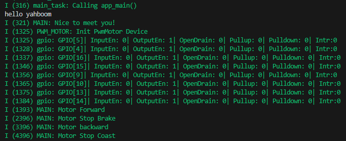
5. Experimental results
The serial port simulator prints the "hello yahboom" greeting. After the car robot is elevated, observe the four-way motors of the car. First, it rotates forward for 1 second at the same time, then brakes and stops for 1 second, then rotates backward for 1 second, and then slides to stop for 1 second. This goes back and forth. At the same time, in the serial port simulator It also prints the current motor status.