Partition table and memory
Partition table and memory1. Experimental purpose2. Hardware connection3. Core code analysis4. Compile, download and flash firmware5. Experimental results
1. Experimental purpose
Use the ESP32S3 core module of the microROS control board to learn the function of ESP32 custom partition table.
2. Hardware connection
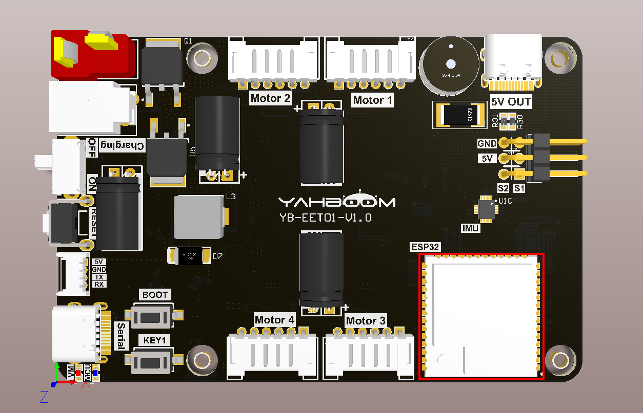
As shown in the figure below, the microROS control board integrates the ESP32-S3-WROOM-1U-N4R2 core module. It not only has internal space, but also has an additional 4MB FLASH program space and 2MB PSRAM memory space. You only need to connect the type-C data cable Connect the computer to the microROS control board as a firmware burning function.
3. Core code analysis
The virtual machine path corresponding to the program source code is as follows
~/esp/Samples/esp32_samples/partition_table
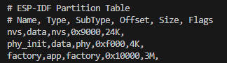
Create a new partitions.csv file in the project root directory and add the following content.
xxxxxxxxxx# Name, Type, SubType, Offset, Size, Flags# Note: if you have increased the bootloader size, make sure to update the offsets to avoid overlapnvs, data, nvs, 0x9000, 0x6000,phy_init, data, phy, 0xf000, 0x1000,factory, app, factory, 0x10000, 3M,
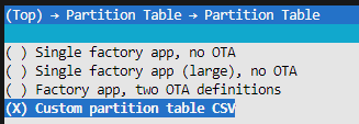
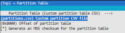
Then open the IDF configuration tool and specify the partition table as partitions.csv.
4. Compile, download and flash firmware
Use a Type-C data cable to connect the virtual machine/computer and the microROS control board. If the system pops up, choose to connect to the virtual machine.
Activate the ESP-IDF development environment. Note that every time you open a new terminal, you need to activate the ESP-IDF development environment before compiling the firmware.
xxxxxxxxxxsource ~/esp/esp-idf/export.sh
Enter the project directory
xxxxxxxxxxcd ~/esp/Samples/esp32_samples/partition_table
Compile project
xxxxxxxxxxidf.py build
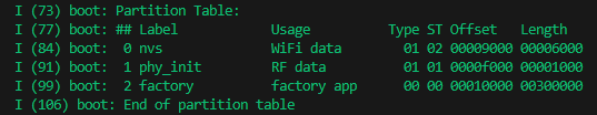
You can see that the partition table printed during compilation is consistent with the partitions.csv file.
Flash and open the serial port simulator
xxxxxxxxxxidf.py flash monitor
If you need to exit the serial port simulator, press Ctrl+].
5. Experimental results
The serial port simulator prints the "hello yahboom" greeting.
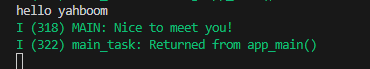
Then slide the mouse wheel upward to view the printed system information. You can see the partition table content displayed in the boot: Partition Table column, which is consistent with the content of partitions.csv in the project root directory.