11. Nine-axis attitude sensor to obtain data
11. Nine-axis attitude sensor to obtain data 11.1. Experimental purpose 11.2. Configuration pin information 11.3. Analysis of the experimental flow chart 11.4. core code explanation 11.5. Hardware connection 11.6. Experimental effect
11.1. Experimental purpose
Use the GPIO port of STM32 to simulate IIC communication, read the raw data of the nine-axis attitude sensor MPU9250, and print it out through the serial port assistant.
11.2. Configuration pin information
- Import the ioc file from the Serial project and name it Read_IMU.
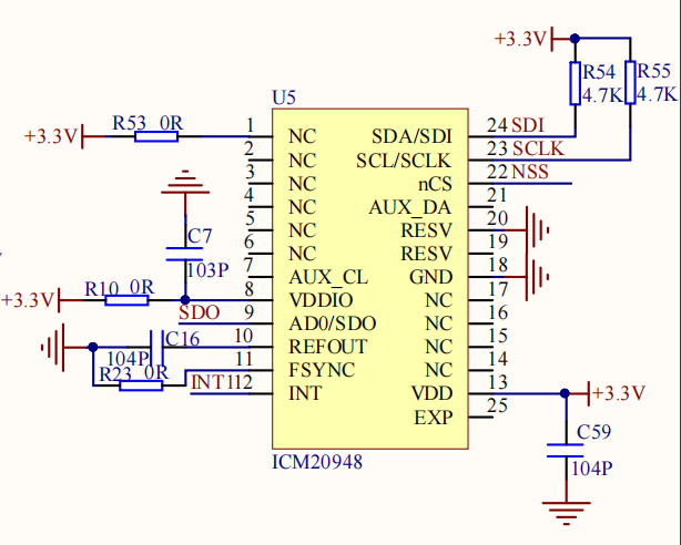
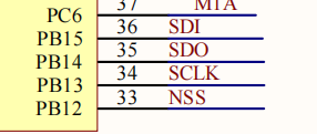
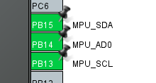
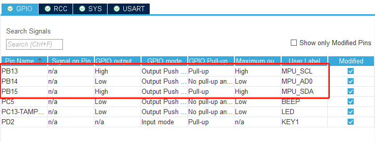
According to the schematic diagram, the SDA/SDI pin of the nine-axis attitude sensor is connected to PB15, the SCL/SCLK pin is connected to PB13, and the AD0/SDO pin is connected to PB14.
- Set PB13, PB14 and PB15 as output mode, the specific parameters are as shown in the figure below:
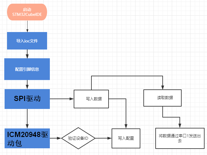
11.3. Analysis of the experimental flow chart
11.4. core code explanation
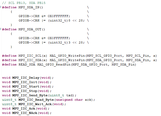
- Create new bsp_mpuiic.h and bsp_mpuiic.c, and add the following content to bsp_mpuiic.h:
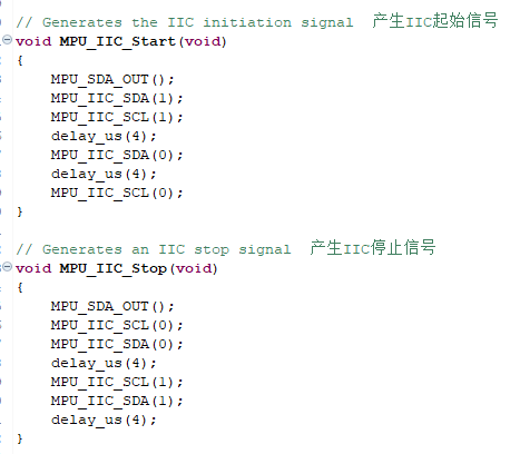
- Create the following content in the bsp_mpuiic.c file:
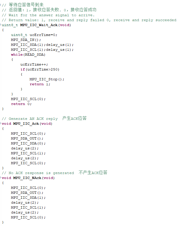
According to the content of the IIC protocol, MPU_IIC_Start() generates the IIC start signal, and MPU_IIC_Stop() generates the IIC stop signal.
3.IIC response correlation function.
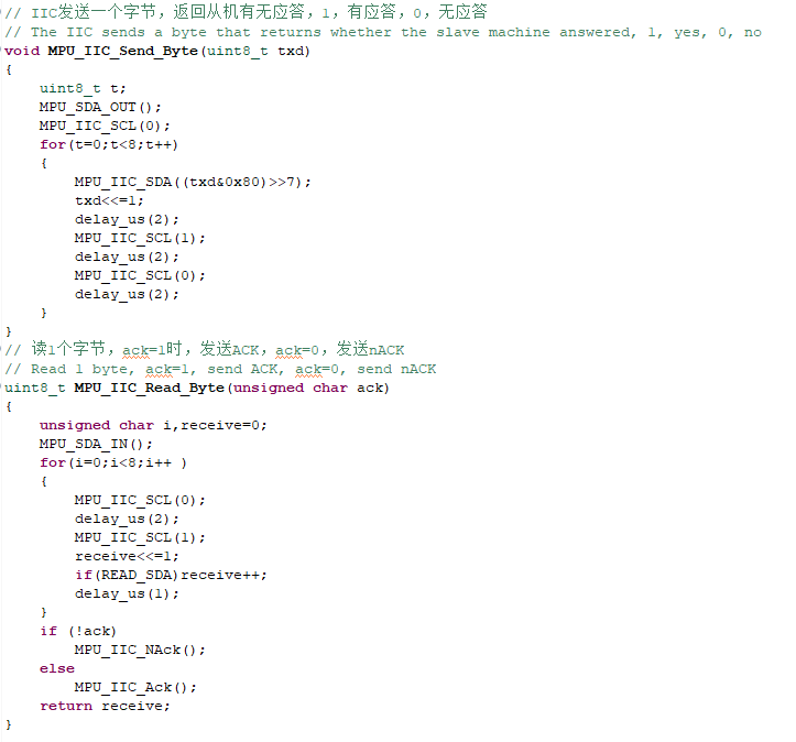
4.IIC send and read data related functions.
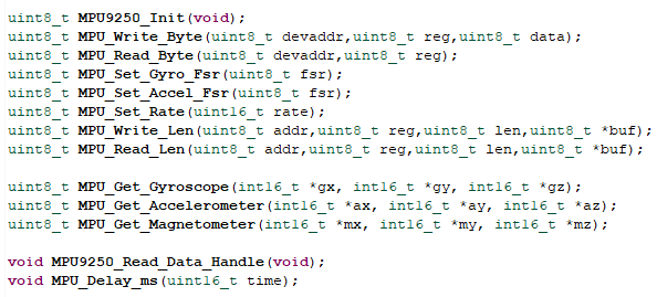
- Create new bsp_mpu9250.h and bsp_mpu9250.c, and add the following content to bsp_mpu9250.h:
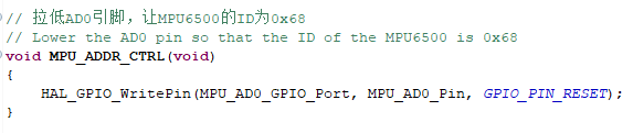
- Add the following related functions in bsp_mpu9250.c.
Pull the AD0 pin low to make the ID of the MPU6500 0x68.
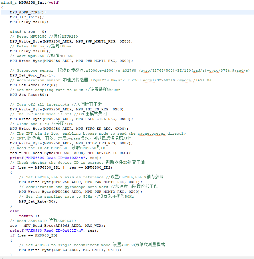
Initialize MPU9250, return value: 0, success, other, error code
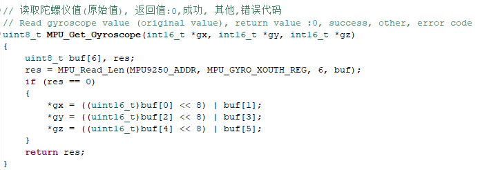
Read the gyroscope value (original value), return value: 0, success, other, error code
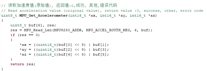
Read acceleration value (original value), return value: 0, success, other, error code
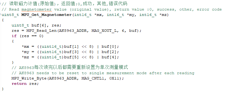
Read magnetometer value (raw value), return value: 0, success, other, error code
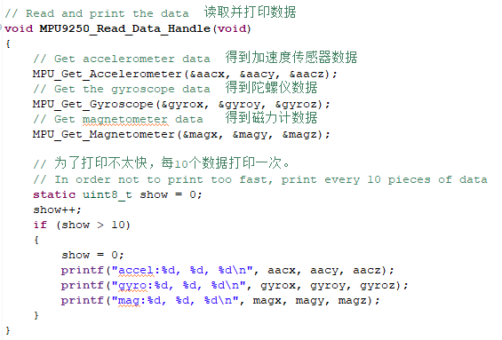
Read and print data, called every 10ms.
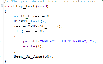
- Add the content of initializing MPU9250 in the Bsp_Init() function, if the initialization fails, stop the program.
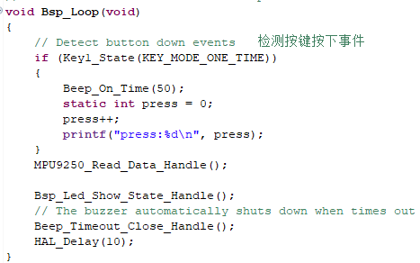
- Add the function of reading MPU9250 data in the Bsp_Loop() function.
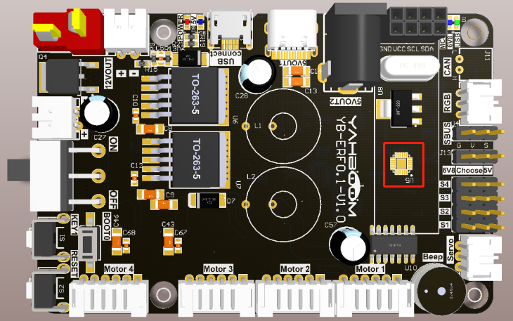
11.5. Hardware connection
The MPU9250 nine-axis attitude sensor has been soldered on the expansion board, so there is no need to manually connect the device.
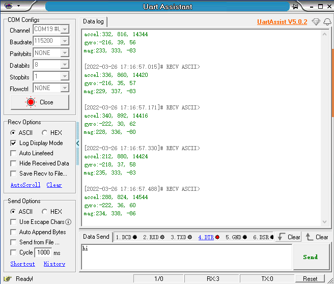
11.6. Experimental effect
After the program is programmed, the LED light flashes every 200 milliseconds. Open the serial port assistant (the parameters are as shown in the figure below), you can see that the serial port assistant has been printing the data of the MPU9250's accelerometer accel, gyroscope gyro, and magnetometer mag.