6. Bind device ID
6. Bind device ID6.1. Device view command6.2. Device binding6.2.1, Astra camera binding6.2.2, PCB and radar binding6.3. Introduction to rule file syntax6.4. Bind USB port
When the robot uses two or more USB serial devices, the corresponding relationship between the device name and the device is not fixed, but is assigned in sequence according to the order in which the devices are connected to the system. Inserting one device first and then another device can determine the relationship between the device and the device name, but it is very troublesome to plug and unplug the device every time the system starts. The serial port can be mapped to a fixed device name. Regardless of the insertion order, the device will be mapped to a new device name. We only need to use the new device name to read and write the device.
6.1. Device view command
Device ID view
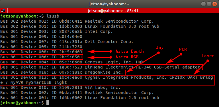
lsusb
As can be seen from the picture below, Astra has an official document for binding the device to the ID number of each device. Generally, the controller does not need to be bound, and it can mainly be bound to the PCB and radar.
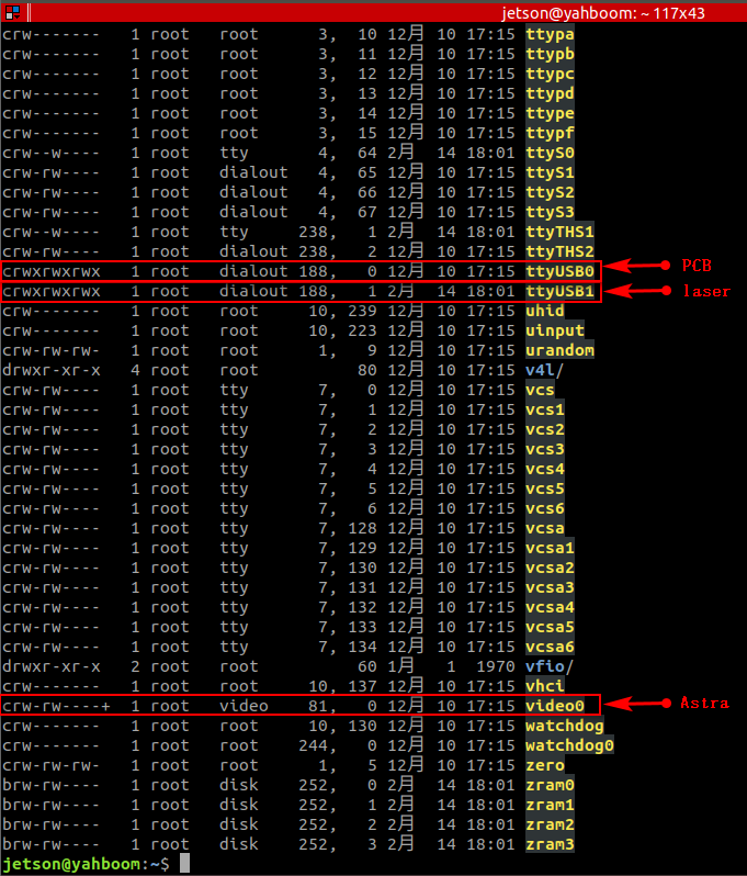
View device number
xxxxxxxxxxll /dev/
6.2. Device binding
6.2.1, Astra camera binding
The binding rule file of the Astra camera is [56-orbbec-usb.rules], which is provided by the Astra manufacturer. AstraPro Plus is used for demonstration here.
Place the [56-orbbec-usb.rules] file in the /etc/udev/rules.d directory of the main control
That is, the following location:
xxxxxxxxxx/etc/udev/rules.d/56-orbbec-usb.rules
Then execute the following command to refresh the USB rules to bind the Astra camera to take effect.
xxxxxxxxxxsudo udevadm control --reload-rules && sudo udevadm trigger
Check whether the binding is successful:
xxxxxxxxxxjetson@ubuntu:~$ ll /dev/astra*lrwxrwxrwx 1 root root 15 May 5 17:42 /dev/astradepth -> bus/usb/001/007 #Port representing depthlrwxrwxrwx 1 root root 15 May 5 17:42 /dev/astrauvc -> bus/usb/001/009 #Represents the RGB portPrinting as above indicates that the binding is successful.
6.2.2, PCB and radar binding
Enter the rules.d directory
xxxxxxxxxxcd /etc/udev/rules.d/Create a new [usb.rules] file and edit it
xxxxxxxxxxsudo vim usb.rulesWrite the following
xxxxxxxxxxKERNEL=="ttyUSB*", ATTRS{idVendor}=="1a86", ATTRS{idProduct}=="7523", MODE:="0777", SYMLINK+="myserial"KERNEL=="ttyUSB*", ATTRS{idVendor}=="10c4", ATTRS{idProduct}=="ea60", MODE:="0777", SYMLINK+="rplidar"
Save and exit, make the rules take effect, and execute on the main control:
xxxxxxxxxxsudo udevadm control --reload-rules && sudo udevadm trigger
Check whether the binding is successful:
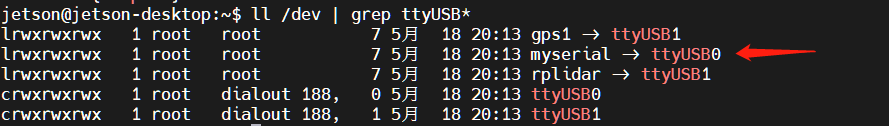
xxxxxxxxxxjetson@jetson-desktop:/etc/udev/rules.d$ ll /dev | grep ttyUSB*lrwxrwxrwx 1 root root 7 May 18 20:13 gps1 -> ttyUSB1 #This comes with the system, don’t worry about itlrwxrwxrwx 1 root root 7 May 18 20:13 myserial -> ttyUSB0 #pcb is bound to the ttyUSB0 portlrwxrwxrwx 1 root root 7 May 18 20:13 rplidar -> ttyUSB1 #The radar is bound to the ttyUSB1 portcrwxrwxrwx 1 root dialout 188, 0 May 18 20:13 ttyUSB0crwxrwxrwx 1 root dialout 188, 1 May 18 20:13 ttyUSB1
Printing as above indicates that the binding is successful.
6.3. Introduction to rule file syntax
xxxxxxxxxxKERNEL=="ttyUSB*", ATTRS{idVendor}=="1a86", ATTRS{idProduct}=="7523", MODE:="0777", SYMLINK+="myserial"KERNEL=="ttyUSB*", ATTRS{idVendor}=="10c4", ATTRS{idProduct}=="ea60", MODE:="0777", SYMLINK+="rplidar"
parse
xxxxxxxxxxKERNEL #The device name matching the eventATTR{filename} # Match the sysfs attributes of the event device.idVendor # Manufacturer numberidProduct # Product numberSYMLINK # Generate symbolic links for device files under /dev/. Just give this device an alias.MODE # Set permissions for the device.From [6.1], we can see that the PCB device number is [ttyUSB0] and is easy to change. The ID number is [1a86, 7523] and is fixed. [ttyUSB*] means that no matter whether the device number becomes [ttyUSB] in the future, it will be followed by [ 0, 1, 2, 3, 4,...] are all bound to [myserial]; the radar device [ttyUSB1] is the same; the same is true for other devices that need to be bound.
Note: When taking an alias, do not take some device names that already exist in the system, otherwise it will fail.
6.4. Bind USB port
The above situations are all different ID numbers. If the ID numbers of the radar and PCB are the same, or there are two or more PCBs (radars) with the same ID, the above binding will be confusing. For example: This situation will occur if the radar and PCB have been bound and the voice control board needs to be bound
Then, we need to bind the USB port. After binding, the USB port cannot be changed at will. Each device can only be connected to a fixed USB port.
Binding method, take [ttyUSB0] as an example to check the port of the device at this time
First check the device corresponding to ttyUSB0:
xxxxxxxxxxll /dev | grep ttyUSB*
The device corresponding to ttyUSB0 is: myserial
xxxxxxxxxxudevadm info --attribute-walk --name=/dev/ttyUSB0 | grep devpath
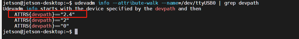
What we need is to modify the myserial rules in the rules file:
xxxxxxxxxx# before fixing:# KERNEL=="ttyUSB*", ATTRS{idVendor}=="1a86", ATTRS{idProduct}=="7523", MODE:="0777", SYMLINK+="myserial"# After modification:KERNEL=="ttyUSB*", ATTRS{devpath}=="2.4", ATTRS{idVendor}=="1a86", ATTRS{idProduct}=="7523", MODE:="0777", SYMLINK+="myserial" Save and exit, make the rules take effect, and execute on the main control:
xxxxxxxxxxsudo udevadm control --reload-rules && sudo udevadm trigger
Check whether the binding is successful:
xxxxxxxxxxjetson@jetson-desktop:/etc/udev/rules.d$ ll /dev | grep ttyUSB*lrwxrwxrwx 1 root root 7 May 18 20:13 gps1 -> ttyUSB1 #This comes with the system, don’t worry about itlrwxrwxrwx 1 root root 7 May 18 20:13 myserial -> ttyUSB0 #pcb is bound to the ttyUSB0 portlrwxrwxrwx 1 root root 7 May 18 20:13 rplidar -> ttyUSB1 #The radar is bound to the ttyUSB1 portlrwxrwxrwx 1 root root 7 May 18 20:13 myspeech -> ttyUSB2 #The voice control board is bound to the ttyUSB2 portcrwxrwxrwx 1 root dialout 188, 0 May 18 20:13 ttyUSB0crwxrwxrwx 1 root dialout 188, 1 May 18 20:13 ttyUSB1crwxrwxrwx 1 root dialout 188, 1 May 18 20:13 ttyUSB2If printed as above, it means that the radar, PCB and voice control board are all bound successfully.
If you don't understand the above binding methods, you can also refer to the content of Chapter 14 of the course document "15. Voice Control Series Course\2. Voice Control Module Port Binding" course.