2. Astra camera calibration
2. Astra camera calibration2.1. Preparation before calibration2.2. Astra calibration2.2.1. Color icon definition2.2.2, ir infrared calibration2.3. Single target setting
Wiki: http://wiki.ros.org/camera_calibration
Official website link: https://orbbec3d.com/develop/
Astra camera: https://github.com/orbbec/ros_astra_camera
Developer community: https://developer.orbbec.com.cn/download.html?id=53
Due to some internal and external reasons of the camera, the image will be greatly distorted, mainly radial deformation and tangential deformation, causing the straight line to become curved. The farther the pixel is from the center of the image, the more serious the distortion will be. In order to avoid errors caused by data sources, the parameters of the camera need to be calibrated. Calibration essentially uses a known and determined spatial relationship (calibration plate) to reversely deduce the inherent and real parameters of the camera (internal parameters) by analyzing the pixels of the photographed pictures.
Disadvantages of infrared depth camera ranging:
(1) It is impossible to accurately measure the distance of black objects because black substances can absorb infrared rays and the infrared rays cannot return, so the distance cannot be measured.
(2) It is impossible to accurately measure the distance of specular objects, because only when the depth camera is on the center vertical line of the specular object, the receiver can receive the reflected infrared rays, which will lead to overexposure.
(3) It is impossible to accurately measure the distance of transparent objects because infrared rays can pass through transparent objects.
(4) Unable to accurately measure distances for objects that are too close. Principle briefly
2.1. Preparation before calibration
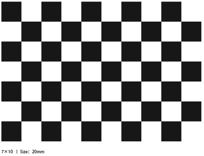
A large [checkerboard] of known dimensions(http://wiki.ros.org/camera_calibration/Tutorials/MonocularCalibration?action=AttachFile&do=view&target=check-108.pdf). This tutorial uses a 9x6 checkerboard and a 20mm square, which needs to be flattened during calibration.
The calibration uses the internal vertices of the checkerboard, so a "10x7" checkerboard uses the internal vertex parameters "9x6", as shown in the example below.
Any calibration board can be used, as long as the parameters are changed.
An open area without obstacles and calibration board patterns
Monocular camera for publishing images via ROS
Checkerboard (calibration board)
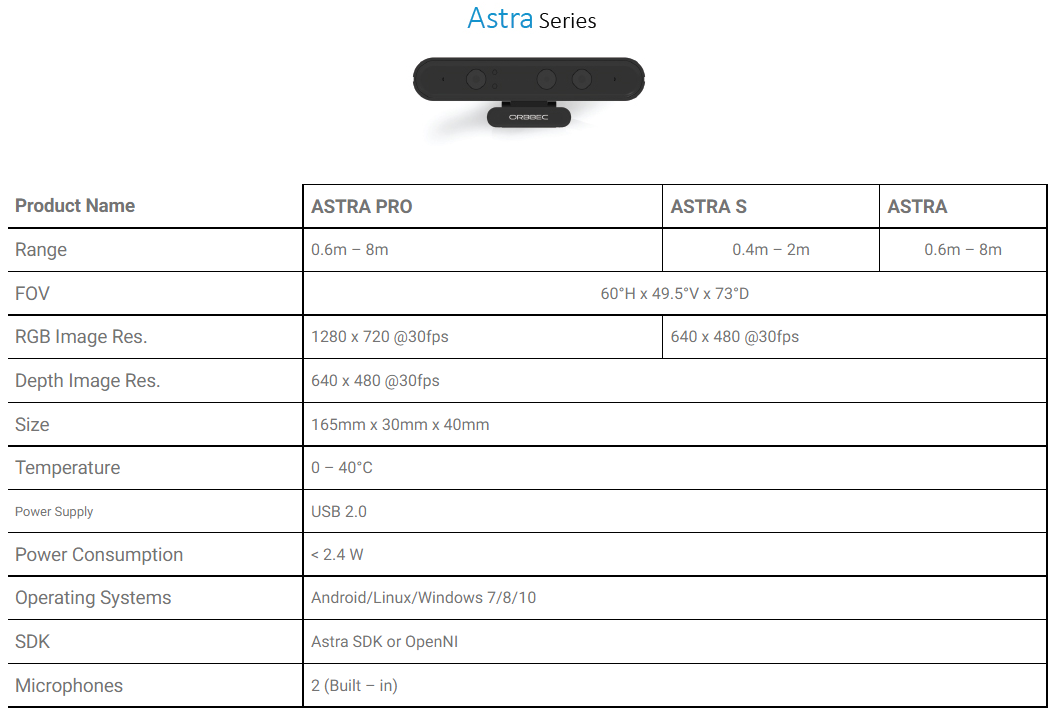
Obi mid-range camera model and corresponding launch file
| Launch file | Launch camera model |
|---|---|
| astra.launch | Astra, Astra S, Astra mini, Astra mini S |
| astraproplus.launch | Astra plus/Astraproplus |
| astrapro.launch | Astra pro |
| embedded_s.launch | Deeyea |
| dabai_u3.launch | Dabai |
| gemini.launch | Gemini |
Device view
lsusb
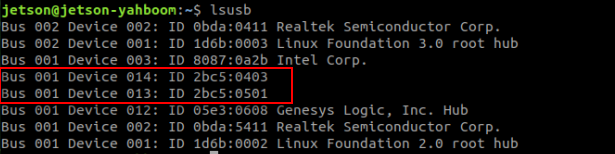
Depth camera ID: [2bc5:0403]
Color camera ID: [2bc5:0501]
The appearance of these two IDs indicates that the device is connected.
2.2. Astra calibration
Start the camera before calibration, and then turn off the camera until all calibrations are completed.
xxxxxxxxxx#Raspberry Pi 5 master needs to enter docker first, please perform this step#If running the script into docker fails, please refer to ROS/07, Docker tutorial~/run_docker.shLaunch Astra Camera
xxxxxxxxxxroslaunch yahboomcar_visual astra_calibration.launch
This startup command includes an IR image conversion node. The conversion is because the IR infrared camera views a 16-bit image during calibration, and the picture cannot be clearly seen. The 16-bit needs to be normalized into a value range of 0-255. 8-bit picture so that you can see it clearly.
View Image Topics
xxxxxxxxxxrostopic list
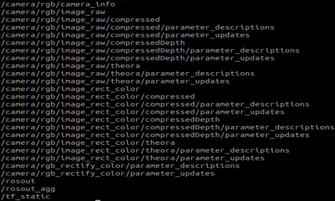
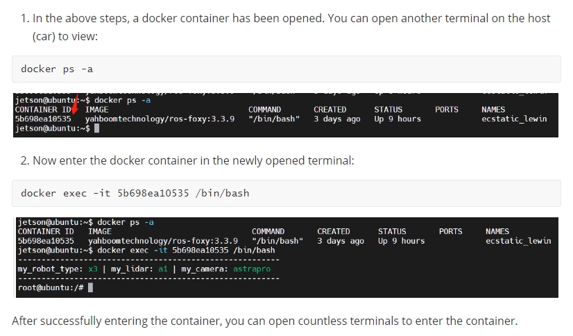
<PI5 needs to open another terminal and enter the same docker container
2.2.1. Color icon definition
Start calibration node
xxxxxxxxxxrosrun camera_calibration cameracalibrator.py image:=/camera/rgb/image_raw camera:=/camera/rgb --size 9x6 --square 0.02size: Calibrate the number of internal corner points of the checkerboard, for example, 9X6, with a total of six rows and nine columns of corner points.
square: The side length of the checkerboard, in meters.
image and camera: Set the image topic published by the camera.
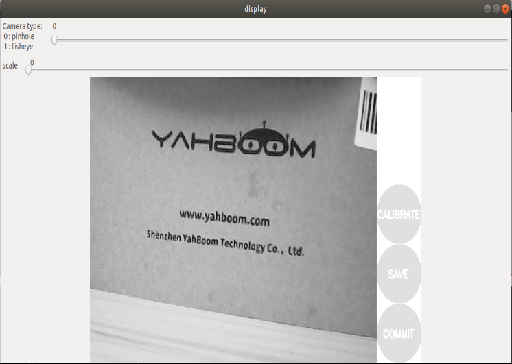
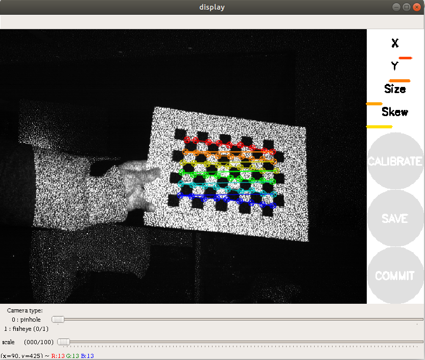
Calibration interface
X: The left and right movement of the checkerboard in the camera field of view
Y: The checkerboard moves up and down in the camera field of view
Size: the movement of the checkerboard back and forth in the camera field of view
Skew: The tilt and rotation of the checkerboard in the camera's field of view
After successful startup, place the checkerboard in the center of the screen and change to different positions. The system will identify it independently. The best situation is that the lines under [X], [Y], [Size], and [Skew] will first change from red to yellow and then to green as the data is collected, filling them as fully as possible.
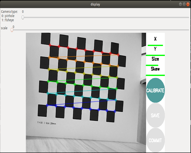
Click [CALIBRATE] to calculate the internal parameters of the camera. The more pictures you have, the longer it will take. Just wait. (Sixty or seventy is enough, too many can easily get stuck).
Click [SAVE] to save the calibration results to [/tmp/calibrationdata.tar.gz].
Click [COMMIT] to write the calibration file into the [.ros/camera_info/rgb_camera.yaml] file. The next time you start the camera, the calibration results will be automatically read.
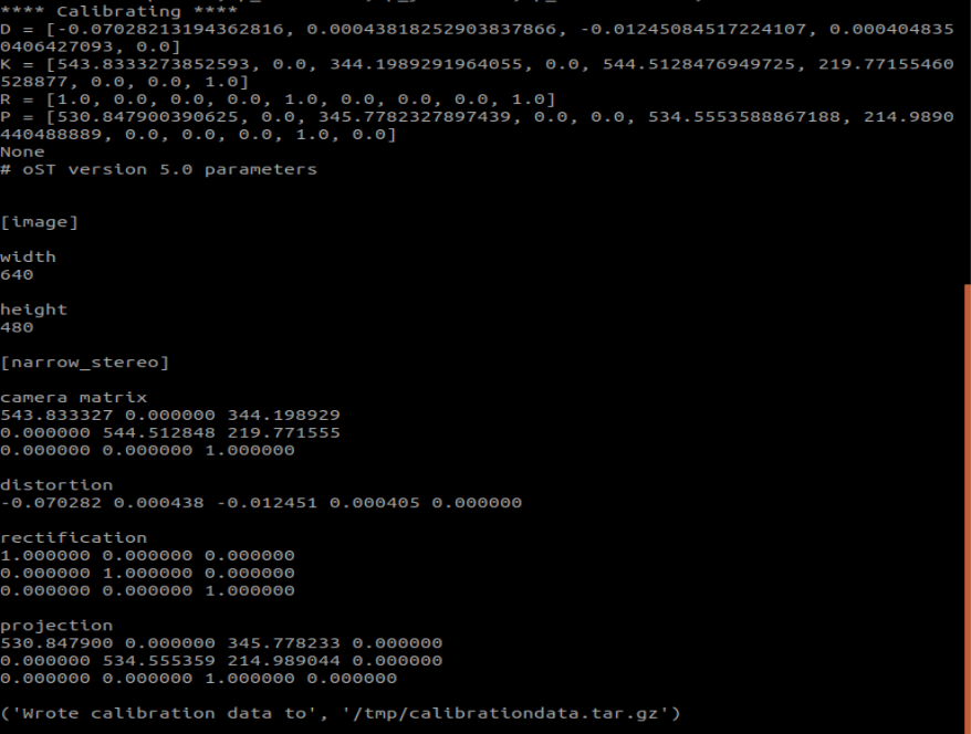
After the calibration is completed, you can move out the [/tmp/calibrationdata.tar.gz] file to see the content.
xxxxxxxxxxsudo mv /tmp/calibrationdata.tar.gz ~After decompression, there are the image just calibrated, an ost.txt file and an ost.yaml file.
2.2.2, ir infrared calibration
After the data normalization problem is dealt with, another problem will arise. Because the RGBD camera, which uses structured light as the depth imaging principle, the infrared light projected by it is a special disordered spot, causing the infrared receiving device to be unable to receive clear and complete images. screen content.
At this time we can have several special processing methods:
Forcibly find various angles and let the camera find the corners as much as possible (poor accuracy)
Spread the infrared light spots evenly by pasting some frosted translucent paper in front of the red hair emitter (moderate accuracy, more convenient)
Block the infrared projection camera and use an external infrared camera to fill in the light (high accuracy, additional equipment is required)
Choose the processing method according to your needs.
Start calibration node
xxxxxxxxxxrosrun camera_calibration cameracalibrator.py image:=/camera/ir/image_mono8 --size 9x6 --square 0.02size: Calibrate the number of internal corner points of the checkerboard, for example, 9X6, with a total of six rows and nine columns of corner points.
square: The side length of the checkerboard, in meters.
image and camera: Set the image topic published by the camera.
The following operations are similar to color camera calibration, changing different poses. The system will identify it independently. The best situation is that the lines under [X], [Y], [Size], and [Skew] will first change from red to yellow and then to green as the data is collected, filling them as fully as possible.
Click [CALIBRATE] to calculate the internal parameters of the camera. The more pictures you have, the longer it will take. Just wait. (Sixty or seventy is enough, too many can easily get stuck).
Click [SAVE] to save the calibration results to [/tmp/calibrationdata.tar.gz].
Click [COMMIT] to write the calibration file into the [.ros/camera_info/ir_camera.yaml] file. The next time you start the camera, the calibration results will be automatically read.
After the calibration is completed, you can move out the [/tmp/calibrationdata.tar.gz] file to see the content.
xxxxxxxxxxsudo mv /tmp/calibrationdata.tar.gz ~After decompression, there are the image just calibrated, an ost.txt file and an ost.yaml file.
2.3. Single target setting
The principle of setting the color map in section [2.2.1] is the same, except that the startup command and topic name are different. This section is suitable for monocular color image calibration.
Start monocular camera
xxxxxxxxxxroslaunch usb_cam usb_cam-test.launch
Start calibration node
xxxxxxxxxxrosrun camera_calibration cameracalibrator.py image:=/usb_cam/image_raw camera:=/usb_cam --size 9x6 --square 0.02
The single-purpose calibration results are stored in the file [.ros/camera_info/head_camera.yaml].