5. Robot URDF model
5.1. URDF overview
Function package reference path:
xxxxxxxxxx/home/yahboom/YBAMR-COBOT-EDU-00001/src/yahboom_navrobo_description/scout_description/launch/display_scout_mini_rviz.launch
5.1.1. Introduction
URDF, the full name of Unified Robot Description Format, translated into Chinese as Unified Robot Description Format, is a robot model file described in XML format, similar to D-H parameters.
xxxxxxxxxx <robot name="yahboomcar"></robot>The first line is a required XML field, describing the XML version information.
The second line describes the current robot name; all information about the current robot is contained in the [robot] tag.
5.1.2, Components
1), link, connecting rod, can be imagined as a human arm.
2), joint, joint, can be imagined as a human elbow.
Relationship between link and joint: two links are connected by joints.
5.1.3, links
1), Introduction
In URDF descriptive language, link is used to describe physical properties.
- Describe visual display,
<visual>tag. - Describe collision properties,
<collision>tag. - Describe physical inertia,
<inertial>tag is not commonly used.
Links can also describe the size of the connecting rod (size)\color (color)\shape (shape)\inertial matrix (inertial matrix)\collision parameters (collision properties), etc. Each Link will become a coordinate system.
2), Sample code: /home/yahboom/YBAMR-COBOT-EDU-00001/src/yahboom_navrobo_description/scout_description/urdf/scout_mini.urdf.xacro ``xml
xxxxxxxxxx3) Tag introduction- origindescribes the pose information; the `xyz` attribute describes the coordinate position in the large environment, and the `rpy` attribute describes its own posture.- messdescribes the quality of `link`.- inertiaInertial reference system, due to the symmetry of the rotational inertia matrix, only 6 upper triangular elements ixx, ixy, ixz, iyy, iyz, izz are needed as attributes.- geometryThe tag describes the shape; the main function of the `mesh` attribute is to load the texture file, and the `filename` attribute is the file address of the texture path. This tag also includes other tag descriptions:```xml<box size="1 2 3"/> <--!box box, the size attribute is used to describe the length, width and height of the box. --><cylinder length="1.6" radius="0.5"/> <--!cylinder cylindrical, the `length` attribute is used to describe the height of the cylinder, and the `radius` attribute is used to describe the radius of the cylinder. --><sphere radius="1"/> <--!sphere spherical, the `radius` attribute is used to describe the radius of the sphere. -->
- material
The tag describes the material; the name attribute is required, can be empty, and can be repeated. The rgba attribute in the [color] tag is used to describe red, green, blue, and transparency, separated by spaces. The color range is [0-1].
5.1.4, joints
1), Introduction
Describes the relationship between two joints, movement position and speed restrictions, kinematic and dynamic properties.
Joint types:
- fixed: Fixed joint. No movement is allowed, it acts as a connection.
- continuous: Rotary joint. It can rotate continuously without rotation angle restrictions.
- revolute: Rotary joint. Similar to continuous, it has rotation angle restrictions.
- prismatic: Sliding joint. Moves along a certain axis with position restrictions.
- floating: Suspended joint. It has six degrees of freedom, 3T3R.
- planar: Planar joint. It allows translation or rotation above the plane orthogonal to the plane.
2) Sample code
xxxxxxxxxx<!-- Laser Joint --><joint name="camera_joint" type="fixed"><parent link="base_link"/><child link="camera_link"/><origin xyz="0.23 0 0.23" rpy="0 0 0"/></joint>In the [joint] tag, the name attribute is a required item, describing the name of the joint, and is unique.
In the [joint] tag, the type attribute is filled in with the six major joint types.
3) Tag introduction
- origin
The sub-tag refers to the relative position of the rotation joint in the coordinate system of parent.
- parent, child
The parent, child sub-tags represent the two links to be connected; parent is a reference object, and child rotates around praent.
- axis
The subtag indicates which axis (xyz) the link corresponding to child rotates around and the amount of rotation around the fixed axis.
- limit
The subtag is mainly used to limit child. The lower and upper attributes limit the range of rotation, the effort attribute limits the force range during the rotation. (positive and negative value, in Newton or N), and the velocity attribute limits the speed of rotation, in meters per second or m/s.
- mimic
Describes the relationship between this joint and existing joints.
- safety_controller
Describes the safety controller parameters. Protects the movement of robot joints.
5.2, URDF visualization
5.2.1, Startup
Stop the self-starting chassis service
xxxxxxxxxxsudo supervisorctl stop ChassisServer
Startup
xxxxxxxxxxroslaunch scout_description display_scout_mini_rviz.launch
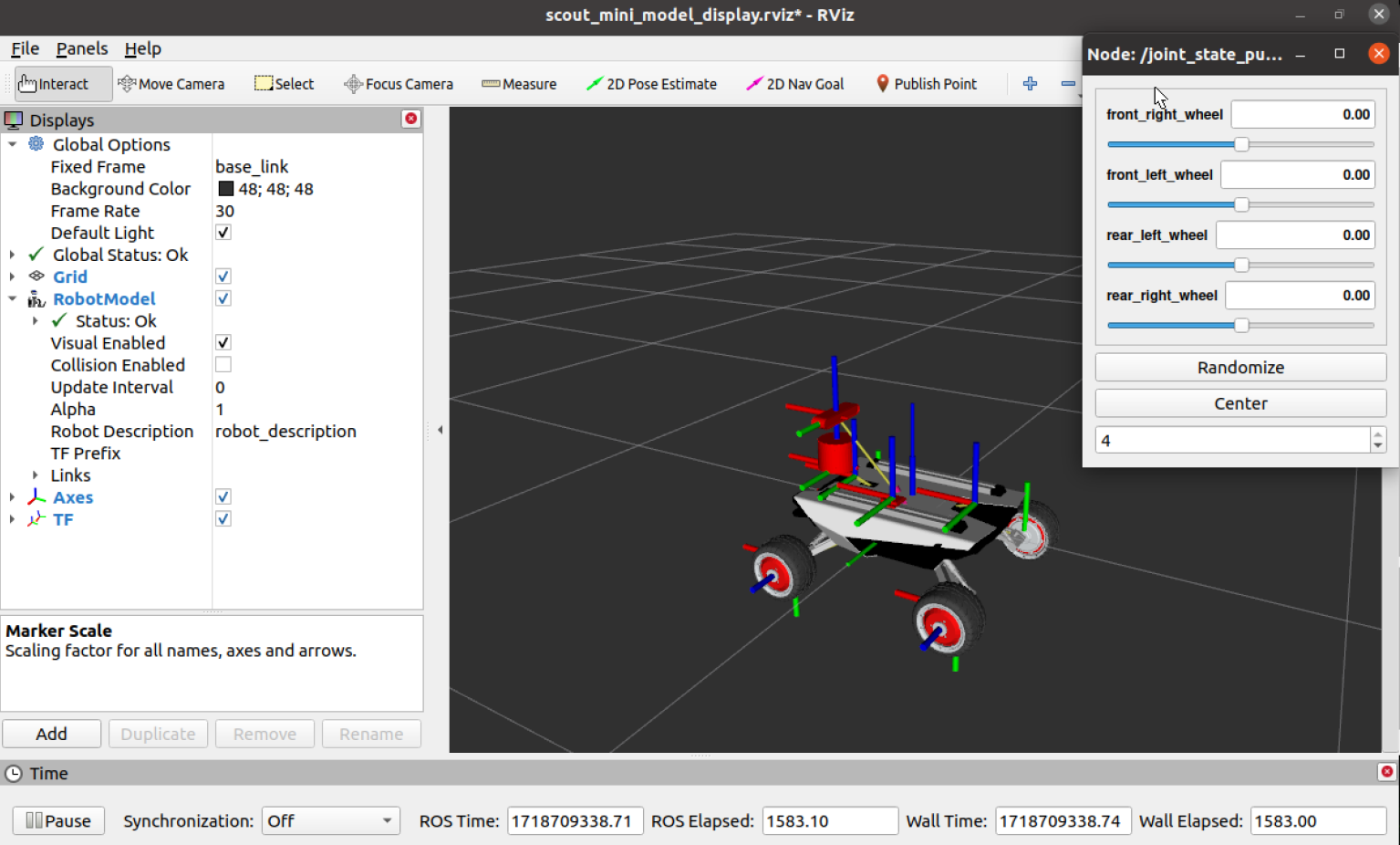
5.2.2, Example image
The red axis is X axis; the green axis is Y axis; the blue axis is Z axis; the coordinate system formed by the three axes is called base coordinate system. Adjusting the [joint_state_publisher_gui] component can control the rotation of the wheel.