Hardware interface
Hardware interface1.Interface distribution2.Supply power interface3.Debugging UART 4.Wired network port5.HDMI interface6.USB interface7.MIPI CSI interface8.Micro SD interface9.Wi Fi antenna interface10.40pin header interface
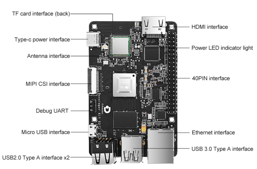
1.Interface distribution
2.Supply power interface
The development board provides a USB Type C power interface as a power supply interface, which requires the use of a power adapter that supports 5V/3A to power the development board. After connecting the power adapter to the development board, the red power indicator light on the development board lights up, indicating that the power supply to the development board is normal.
Note: Please do not use the computer USB interface to power the development board, otherwise it may cause abnormal power outages, repeated restarts, and other situations due to insufficient power supply.
3.Debugging UART
The development board provides a debugging serial port to achieve serial port login and debugging functions.
The parameter configuration of the computer serial port tool is as follows.
- Baud rate: 921600
- Data bits: 8
- Parity: None
- Stop bits: 1
- Flow Control: None
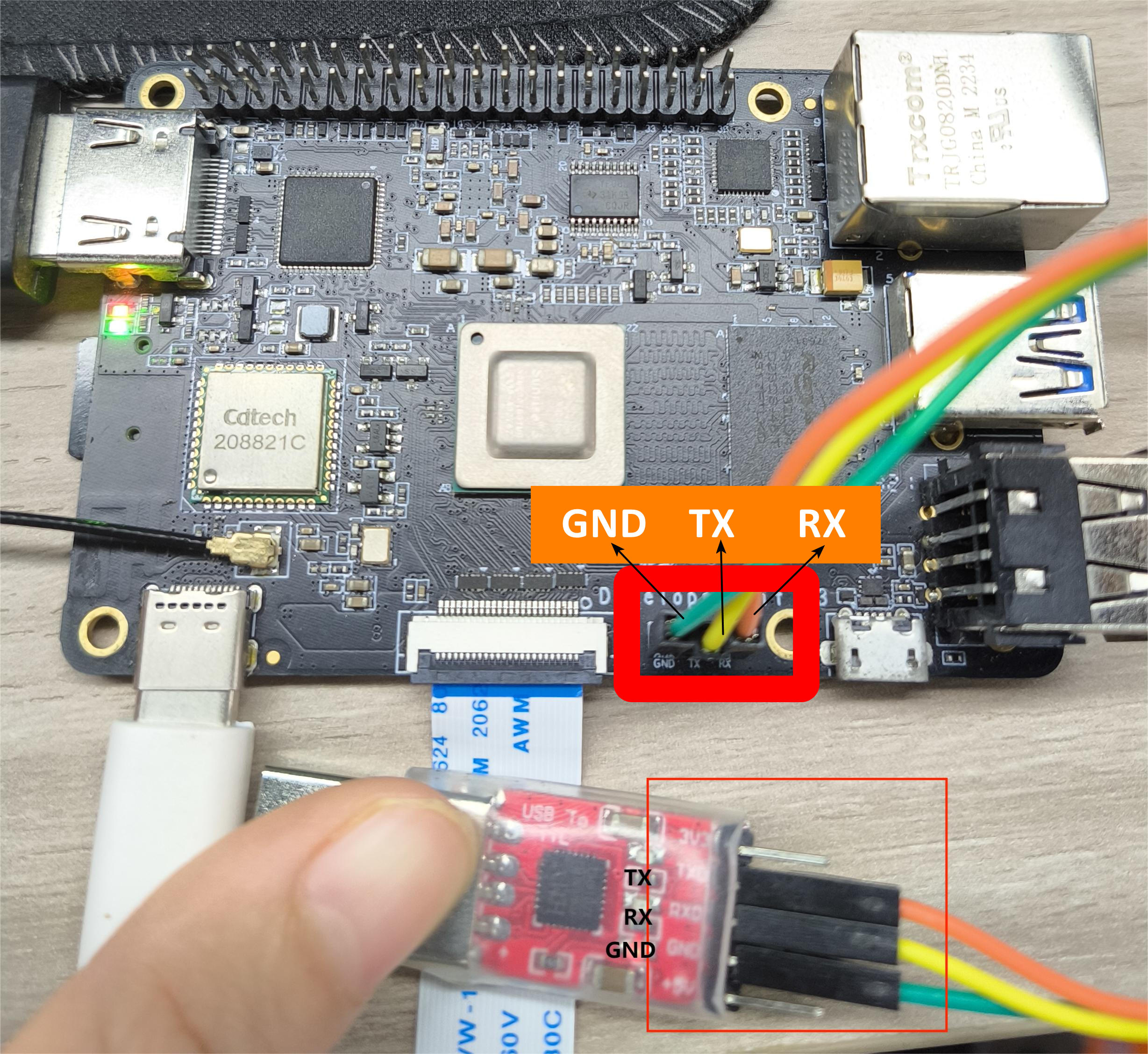
When connecting the serial port, it is necessary to connect the DuPont cable to the development board to debug the serial port, and connect the serial port USB adapter board to the computer.
After the connection is completed, as shown below.
4.Wired network port
The development board provides a Gigabit Ethernet interface that supports 1000BASE-T and 100BASE-T standards. It defaults to static IP mode with an IP address of 192.168.1.10.
To confirm the IP address of the development board, you can log in to the device through the serial port and use the ifconfig command to view the configuration of the eth0 network port.
5.HDMI interface
The development board provides one HDMI interface and supports up to 1080P resolution.
The development board outputs the Ubuntu system desktop (Ubuntu Server version displays the logo icon) on the monitor through the HDMI interface.
In addition, the HDMI interface also supports real-time display of cameras and network streaming functions.
The current display resolutions supported by HDMI interfaces are as follows.
- 1920x1080
- 1280x720
- 1024x600
- 800x480
6.USB interface
Due to the fact that the RDK X3 chip only provides one USB interface, the development board has implemented multiple USB interface extensions through hardware circuits to meet users needs for accessing multiple USB devices.
The interface description is as follows.
| Interface type | Number of interfaces | Interface description |
|---|---|---|
| Micro USB 2.0 | 1 | USB Device mode, used to connect the host to achieve functions such as ADB, Fastboot, UVC, etc |
| USB 2.0 Type A | 2 | USB Host mode, used to connect USB 2.0 peripherals |
| USB 3.0 Type A | 1 | USB Host mode, used to connect USB 3.0 peripherals |
7.MIPI CSI interface
The development board provides one MIPI CSI interface (interface 2), which can realize the access of MIPI cameras.
At present, the development board is compatible with various specifications of camera modules.
The module models and specifications are as follows.
| Serial Number | Sensor | Resolution ratio | FOV | I2C device address |
|---|---|---|---|---|
| 1 | GC4663 | 400W | H:104 V:70 D:113 | 0x29 |
| 2 | JXF37 | 200W | H:62 V:37 D:68 | 0x40 |
| 3 | IMX219 | 800W | H:62 V:37 D:68 | 0x10 |
| 4 | IMX477 | 1200W | H:62 V:37 D:68 | 0x1a |
| 5 | OV5647 | 500W | H:62 V:37 D:68 | 0x36 |
The camera module is connected to the development board through an FPC cable, and attention should be paid to inserting the connector with the blue side facing upwards at both ends of the cable.
Note: It is strictly prohibited to plug in or unplug the camera without powering off the development board, otherwise it may damage the camera module.
8.Micro SD interface
The development board provides one Micro SD memory card interface.
It is recommended to use a storage card with at least 8GB capacity to meet the installation requirements of the Ubuntu operating system and related feature packs.
9.Wi Fi antenna interface
The wireless network of the development board supports two configurations: onboard and external antennas.
In normally , on board antennas can meet usage requirements.
After installing the metal casing on the development board, it is necessary to connect an external antenna to the antenna interface to enhance signal strength.
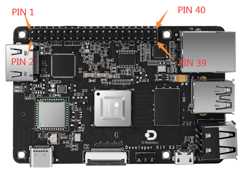
10.40pin header interface
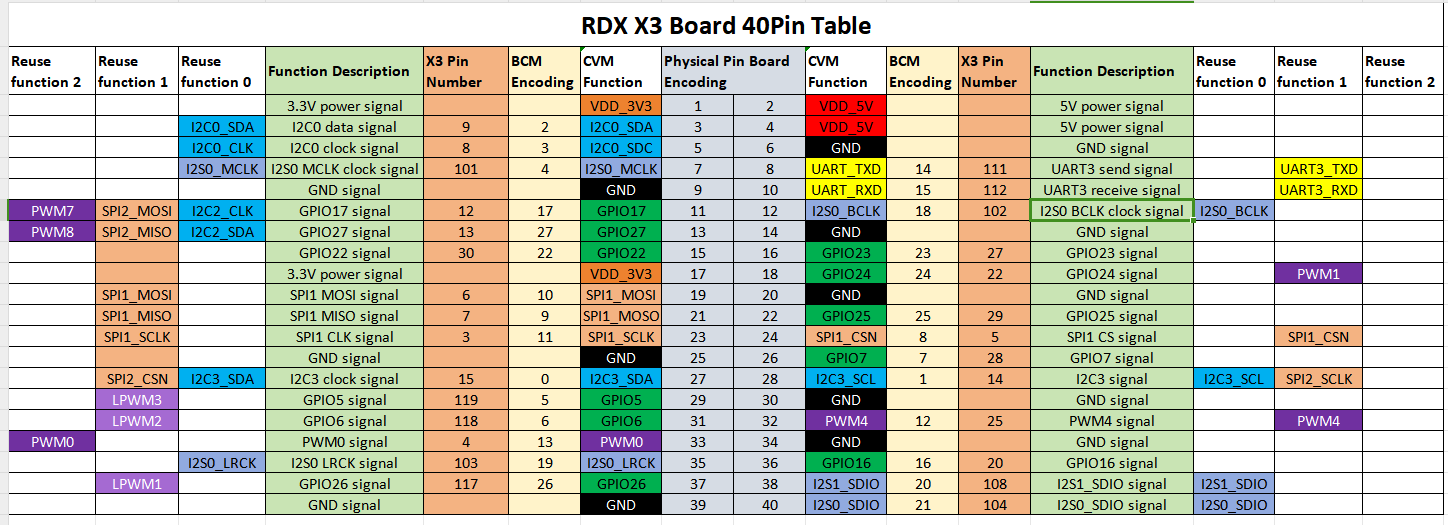
The PIN1 and PIN40 positions on the RDK X3 development board are as follows.