DMA:I2C
DMA:I2CHardware connectionControl principleSoftware configurationPin definitionSoftware codeControl functionExperimental phenomenon
The tutorial demonstrates I2C communication through DMA to control OLED display.
The tutorial only introduces the standard library project code
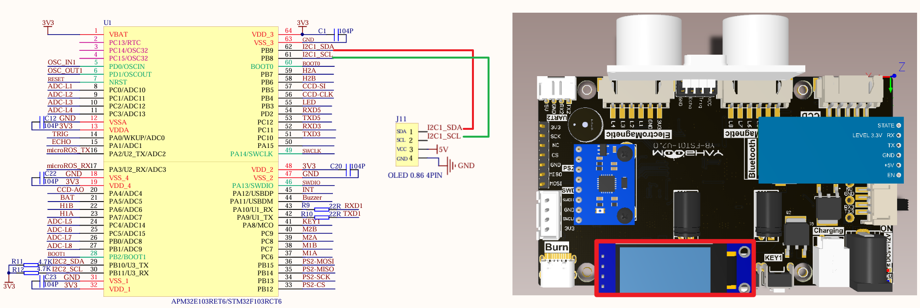
Hardware connection
| Peripherals | Development board | Description |
|---|---|---|
| OLED: VCC | 5V | OLED power supply |
| OLED: GND | GND | OLED common ground |
| OLED: SCL | PB8 | Serial clock line (SCL) |
| OLED: SDA | PB9 | Serial data line (SDA) |
Control principle
xxxxxxxxxxI2C related knowledge will not be introduced, mainly DMA knowledge.
STM32F103RCT6 has two DMA controllers, DMA1 has 7 channels and DMA2 has 5 channels;
It is used for high-speed data transmission between peripherals and memory and between memory and memory.
DMA characteristics
DMA initialization and startup are completed by the CPU, and the transmission process is performed by the DMA controller without CPU participation, thus saving CPU resources for other operations.
DMA1 request for each channel

DMA2 request for each channel
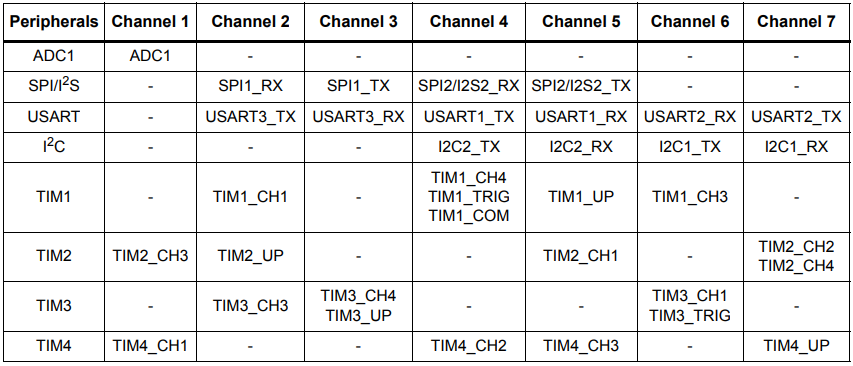
This tutorial uses DMA1 channel 6.
Software configuration
Pin definition
| Main control chip | Pin | Main function (after reset) | Default multiplexing function | Redefine function |
|---|---|---|---|---|
| STM32F103RCT6 | PB8 | PB8 | TIM4_CH3 | I2C1_SCL/CAN_RX |
| STM32F103RCT6 | PB9 | PB9 | TIM4_CH4 | I2C1_SDA/CAN_TX |
Software code
Since the default function of the pin is the ordinary IO pin function, we need to use the redefine function.
xxxxxxxxxxProduct supporting data source code path: Attachment → Source code summary → 1.Base_Course → 15.I2C+DMA
Control function
The tutorial only briefly introduces the code, and you can open the project source code to read it in detail.
OLED_I2C_Init
xvoid OLED_I2C_Init(void){GPIO_InitTypeDef GPIO_InitStructure;I2C_InitTypeDef I2C_InitStructure;RCC_APB1PeriphClockCmd(OLEDI2C_RCC, ENABLE);RCC_APB2PeriphClockCmd(OLED_RCC, ENABLE);//开启复用功能RCC_APB2PeriphClockCmd(RCC_APB2Periph_AFIO, ENABLE);GPIO_PinRemapConfig(GPIO_Remap_I2C1, ENABLE);//PB8——SCL PB9——SDAGPIO_InitStructure.GPIO_Mode = GPIO_Mode_AF_OD;GPIO_InitStructure.GPIO_Pin = OLED_SCL_Pin | OLED_SDA_Pin;GPIO_InitStructure.GPIO_Speed = GPIO_Speed_50MHz;GPIO_Init(OLED_Port, &GPIO_InitStructure);I2C_DeInit(OLEDI2C);I2C1->CR1 |= 0x8000; // 手动清除清BUSYI2C1->CR1 &= ~0x8000;I2C_InitStructure.I2C_Ack = I2C_Ack_Enable;I2C_InitStructure.I2C_AcknowledgedAddress = I2C_AcknowledgedAddress_7bit;I2C_InitStructure.I2C_ClockSpeed = 400000;I2C_InitStructure.I2C_DutyCycle = I2C_DutyCycle_2;I2C_InitStructure.I2C_Mode = I2C_Mode_I2C;I2C_InitStructure.I2C_OwnAddress1 = 0x10; //此地址随便填,不做从机I2C_Init(OLEDI2C, &I2C_InitStructure);I2C_Cmd(OLEDI2C, ENABLE);MY_DMA_Transmit_InitConfig();//DMA初始化OLED_Init();//oled初始化OLED_Draw_Line("oled init success!", 1, true, true);}
MY_DMA_Transmit_InitConfig
xxxxxxxxxxvoid MY_DMA_Transmit_InitConfig(void){RCC_AHBPeriphClockCmd(RCC_AHBPeriph_DMA1, ENABLE); //Enable DMA transferDMA_DeInit(DMA1_Channel6);DMA_InitTypeDef DMA_InitStructer;DMA_InitStructer.DMA_PeripheralBaseAddr = (uint32_t)&I2C1->DR; //Note that do not forget to add the & symbol when taking the address hereDMA_InitStructer.DMA_PeripheralDataSize = DMA_PeripheralDataSize_Byte;DMA_InitStructer.DMA_PeripheralInc = DMA_PeripheralInc_Disable; //The DR register position is fixed, there is only one, so the pointer cannot be moved after the transferDMA_InitStructer.DMA_MemoryBaseAddr = (uint32_t)myData;DMA_InitStructer.DMA_MemoryDataSize = DMA_PeripheralDataSize_Byte;DMA_InitStructer.DMA_MemoryInc = DMA_MemoryInc_Enable; // The pointer on the Data array needs to be incremented continuously so that the data can be sent out in turn, instead of just sending the first one in the arrayDMA_InitStructer.DMA_Mode = DMA_Mode_Normal; // DMA is set to normal modeDMA_InitStructer.DMA_DIR = DMA_DIR_PeripheralDST; // Send data to peripheralsDMA_InitStructer.DMA_M2M = DMA_M2M_Disable; // Note that software triggering is not applicableDMA_InitStructer.DMA_BufferSize = 2;DMA_InitStructer.DMA_Priority = DMA_Priority_VeryHigh;DMA_Init(DMA1_Channel6,&DMA_InitStructer);NVIC_InitTypeDef NVIC_InitStructure;//Interrupt priority NVIC settingsNVIC_InitStructure.NVIC_IRQChannel = DMA1_Channel6_IRQn; //DMA interruptNVIC_InitStructure.NVIC_IRQChannelPreemptionPriority = 0; //Preempt priority level 0NVIC_InitStructure.NVIC_IRQChannelSubPriority = 1; //Sub priority level 1NVIC_InitStructure.NVIC_IRQChannelCmd = ENABLE; //IRQ channel is enabledNVIC_Init(&NVIC_InitStructure); //Initialize NVIC registers/* Enable DMA Channel6 complete transfer interrupt */DMA_ITConfig(DMA1_Channel6, DMA_IT_TC, ENABLE);}
OLED_DMA_Transfer
xxxxxxxxxxvoid OLED_DMA_Transfer(void){DMA_Cmd(DMA1_Channel6, DISABLE); //Disable the channel indicated by DMADMA_SetCurrDataCounter(DMA1_Channel6, 2); //The size of the DMA buffer of the DMA channelDMA_Cmd(DMA1_Channel6, ENABLE); //Enable the channel indicated by DMA// I2C_DMACmd(OLEDI2C, ENABLE);// while(!DMA_GetFlagStatus(DMA1_FLAG_TC6));}
Experimental phenomenon
The [I2C+DMA.hex] file generated by the project compilation is located in the OBJ folder of the [I2C+DMA] project. Find the [I2C+DMA.hex] file corresponding to the project and use the FlyMcu software to download the program to the development board.
After the program is successfully downloaded: OLED will display oled init success! and I2C + DMA Class! content.