8-channel line tracking module usage
8-channel line tracking module usage0. Schematic diagram of 8-channel line tracking module1. Protocols supported by 8-channel line tracking module2. Calibration steps for 8-channel line tracking module3. 8-way module protocol
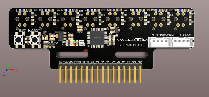
0. Schematic diagram of 8-channel line tracking module
front:
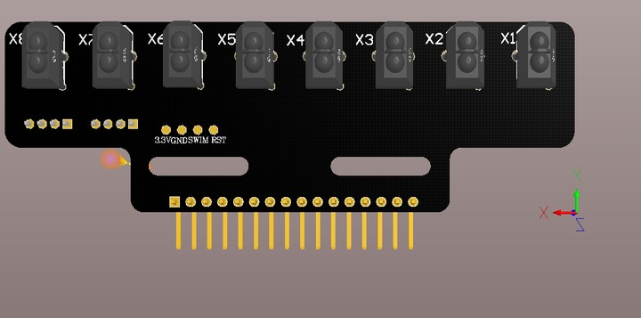
 Reverse:
1. Protocols supported by 8-channel line tracking module
- Direct IO level reading (can only obtain digital values)
- USART method acquisition (can obtain analog values and digital values)
- I2C method acquisition (can only obtain digital values)
2. Calibration steps for 8-channel line tracking module
- First, power on the module and wait for at least 20 seconds. The main purpose is to stabilize the probe. (You need to wait every time you power on the module)
- If it is the first time to power on the module and it has not been calibrated, the red light of the module will keep flashing. (You need to enter the calibration mode at this time)
- Long press the key1 button on the board, wait for the red light of the board to light up, and enter the calibration mode. Warm Tips: After entering the calibration mode, the light on the probe will no longer respond to the black and white lines, that is, it will not take effect. Wait until the calibration is completed before it will respond.
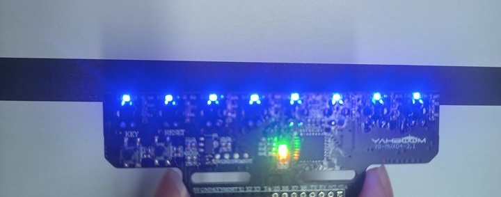
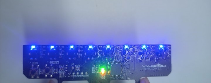
- Place the probe on the black line according to the height you use (at what height you run it, that is, at what height you calibrate it), stop for 3 seconds and wait for the data to stabilize (do not move the probe during this period), as shown in the figure
- After 3 seconds, lightly press key1 to record the value of the black line detected by the probe. After recording, the red light on the board will flash quickly and then return to normal.
- Then, place the probe on the white line and wait for 3 seconds for the data to stabilize (do not move the probe during this period), as shown in the figure
- After 3 seconds, press key1 to record the value of the white line detected by the probe. After recording, the red light on the board will flash quickly.
- If the calibration is successful, the red light on the board will go out and enter the detection mode; if it fails, the red light on the board will flash slowly and continuously, and recalibration is required.
If you accidentally enter the calibration mode, you can press the reset button to reset the module or quickly double-click the key1 button to exit the calibration.
The values after each calibration are saved when the power is turned off, and can be used directly next time the machine is turned on, without the need to calibrate each time. Unless you change to a different environment and altitude, you need to recalibrate at this time.
3. 8-way module protocol
- Serial port Upper computer uses commands ($,,#)
- Master control mode commands to the module
- $calibration switch, analog data transmission switch, digital transmission switch# eg:
- Need to calibrate: $1,0,0# (This command is only to enter the calibration, you still need to press the onboard button to read the value of the black and white lines)
- Need digital type: $0,0,1#
- Need analog type: $0,1,0#
- Need digital and analog type: $0,1,1#"
The data sent by the module is sent to the main control The default setting is to not send data when powered on. Only when the corresponding command is received will the command be sent continuously.
- Digital type $D,x1:0,x2:0,x3:0,x4:0,x5:0,x6:0,x7:0,x8:0#
- Analog type $A,x1:4096,x2:4096,x3:4096,x4:4096,x5:4096,x6:4096,x7:4096,x8:4096#
- I2C
Module device I2C address 0x12
| Register Description | R/W | value | Remark |
|---|---|---|---|
| 0x01 | W | 1/0 | "1: Enter calibration 0: Exit calibration (default)" |
| 0x30 | R | 0-255 | "8 infrared status values (0-1) 0x00-0xFF 11111111 (binary) Each bit represents a probe x1-x8 |
eg: X1 lights up (on the black line) and other probe lights are off B01111111 -> 0x8F ->127 X2 and X4 lights up, others are off B10101111 -> 0xAF ->175"