Inverse kinematics analysis
Inverse kinematics analysis2.1 Modeling of single leg inverse kinematics2.2 Foot-end trajectory planning
2.1 Modeling of single leg inverse kinematics
In the quadruped robot motion control problem, the trajectory planning of the foot end should be carried out first, and then instead of directly specifying the joint angles. This requires the inverse kinematics solution, according to the given foot trajectory, to solve the corresponding joint angles, and use it as the input of the steering gear, so that the foot can move according to the specified trajectory.
According to formula (2-10), it can be obtained by arranging.
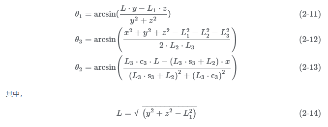
According to equations (2-11) to (2-14), given the coordinates of the foot end, the joint angles corresponding to the left front leg can be solved. The inverse kinematics solution algorithm is transplanted into webot, so that the quadruped robot moves forward in a diagonal gait, and the motion trajectory of the foot end is a sine curve.
The simulation results are shown in the figure below. The quadruped robot alternately lifts the opposite legs and steps forward in a sinusoidal trajectory, which proves the correctness of the inverse kinematics algorithm.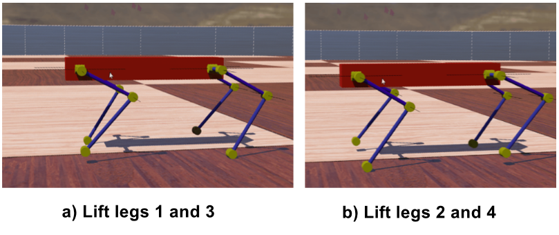 Simulate diagonal gait in webots
2.2 Foot-end trajectory planning
The trajectory planning of the foot end of the quadruped robot is an important part of the free gait planning.The trajectory of the foot end affects the accuracy of the quadruped robot's step, the stability of walking, and the impact force of the foot end, and also affects the obstacle-surmounting ability of the quadruped robot.
In the periodic gait, the movement of the quadruped robot pursues rapidity, so the speed of the foot end is relatively large, and the smoothness of the optimal target trajectory of the foot end trajectory planning is achieved. In the free gait, the movement of the quadruped robot pursues stability and obstacle clearance. Therefore, a rectangular swing trajectory is designed in this paper, so that the swing leg maintains a certain height with the support surface during the movement process and overcomes possible obstacles on the ground as much as possible.
As shown in the figure below, the rectangular swing trajectory is divided into three stages: vertical lift stage, horizontal movement stage and vertical drop stage. Assume that the coordinates of the starting foot point in the body coordinate system are (x~s~, y~s~, z~n~), and the coordinates of the target foot point are (x~g~, y~g~, z~n~) , the swinging leg will vertically lift a certain height z~m~, then move horizontally to just above the landing point, and finally fall vertically. In order to reduce the impact force brought by the landing of the foot, it is necessary to allocate more movement time to the vertical descent stage in the planning to reduce the speed of the foot movement. Let the time required for a single swing be T~m~, the time used for the vertical lifting stage is T~m~/4, the time for the horizontal movement stage is T~m~/4, and the time for the vertical falling stage is T~m~/2 . 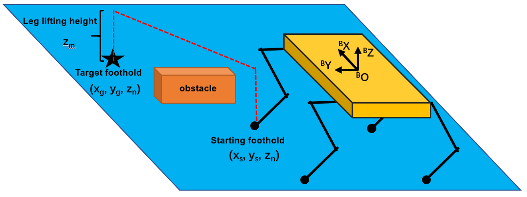
Schematic diagram of a quadruped robot for obstacle crossing
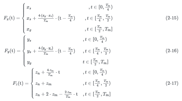
Then the equation of the motion trajectory of the foot end of the quadruped robot in the body coordinate system can be obtained:
In the actual control process, the input value of the inverse kinematics solution is the coordinates of the foot end, so it is necessary to discretize the end trajectory,If the number of discretized control points is too small, the actual motion trajectory will not track the desired trajectory well, because the actual trajectory of the end between two control points is a curve.Assuming that only the end position of each stage is taken for inverse solution control, as shown in the figure below, the blue square in the figure is the taken control point, the red solid line represents the desired trajectory, and the blue dotted line represents the actual motion trajectory.It can be seen that the actual motion trajectory has a large deviation,In the horizontal translation stage, the height of the leg lift is decreased, which affects the obstacle-surmounting performance, and in the vertical descent stage, it deflects to contact the ground, which will bring lateral impact to the quadruped robot and affect the stability. 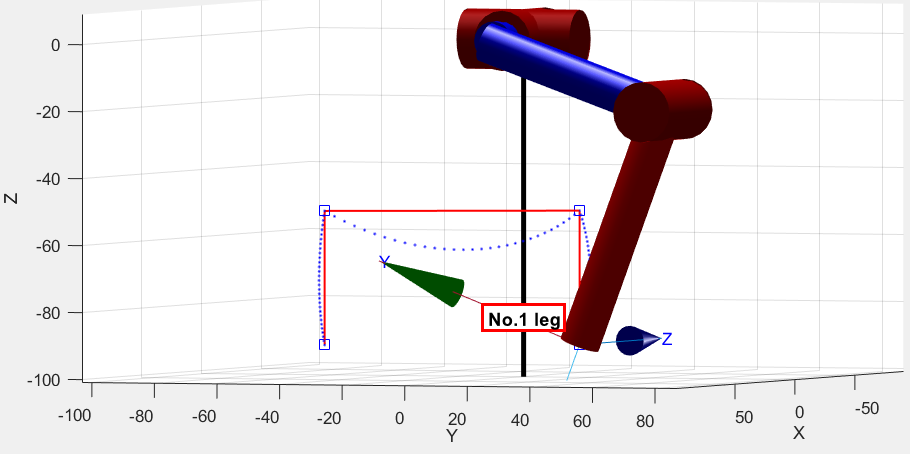
Only take the actual foot movement trajectory of the three control points
Therefore, it is necessary to take an appropriate amount of control points on the trajectory, 10 control points on each of the vertical upward trajectory and the horizontal movement trajectory, and 20 control points on the vertical downward trajectory, and simulate in matlab again. As shown in the figure below, the actual foot movement trajectory tracks the expected trajectory well. In the actual control process, the settlement results of the control points will be sent sequentially at a frequency of 20Hz, which not only satisfies the trajectory tracking accuracy, but also controls the speed of the foot end in the vertical descent stage.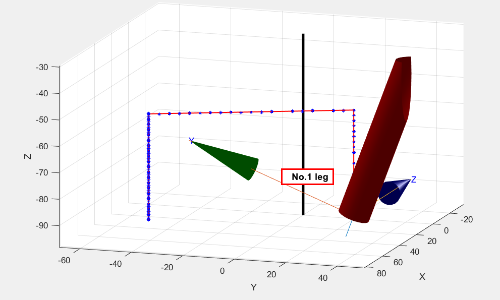
Take the actual foot movement trajectory of reasonable discrete points