STM32 basic routines
STM32 basic routinesHardware preparationExperimental purposeHT-10A remote controlSBUS receiverSTM32 projectConfiguration pinROS control board schematicProject pin configurationImplementation principleCore codeSerial port functionSBUS dataMain functionHardware connectionDownload programExperimental phenomenon
Hardware preparation
HT-10A remote controller
SBUS receiver
ROS control board
Experimental purpose
Analyze the SBUS protocol data received by the HT-10A remote controller receiver through the ROS control board, and print the values of each channel through the serial port.
Users need to build the STM32CubeIDE environment by themselves!The engineering source code corresponding to this tutorial is SBUS.zip in the [Software Information] folder
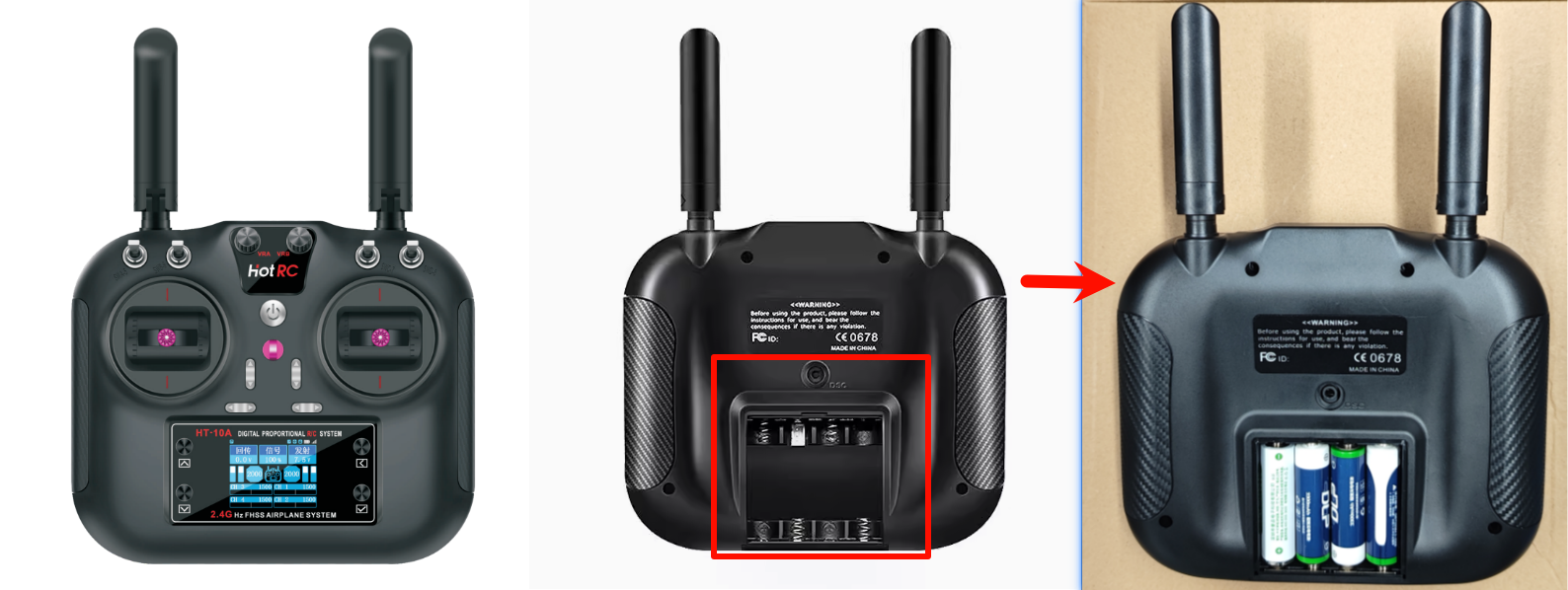
HT-10A remote control
You need to install 4 No. 5 batteries in advance to power the HT-10A remote control:
| HT-10A remote control | Default channel: The remote control does not perform channel mapping |
|---|---|
| CH1 | Right joystick: slide left and right |
| CH2 | Right joystick: slide up and down |
| CH3 | Left joystick: slide up and down |
| CH4 | Left joystick: slide left and right |
| CH5 | SWA channel |
| CH6 | SWB channel |
| CH7 | SWC channel |
| CH8 | SWD channel |
| CH9 | VRA channel |
| CH10 | VRB channel |
SBUS receiver
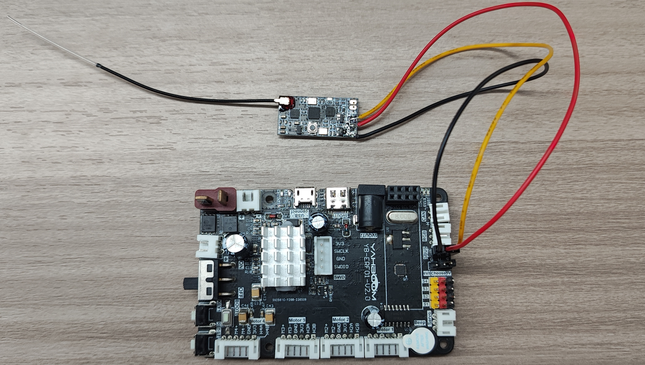
The picture shows the hardware connection between the SBUS receiver and the ROS control board:
| SBUS receiver | ROS control board |
|---|---|
| S | S |
| + | V |
| - | G |

STM32 project
The tutorial only demonstrates the main code and functions: For detailed project code, refer to the [Software Materials] folder.
Configuration pin
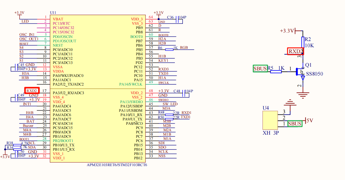
ROS control board schematic
The SBUS interface is connected to the PA3 pin (RX pin of serial port 2) of the ROS control board:
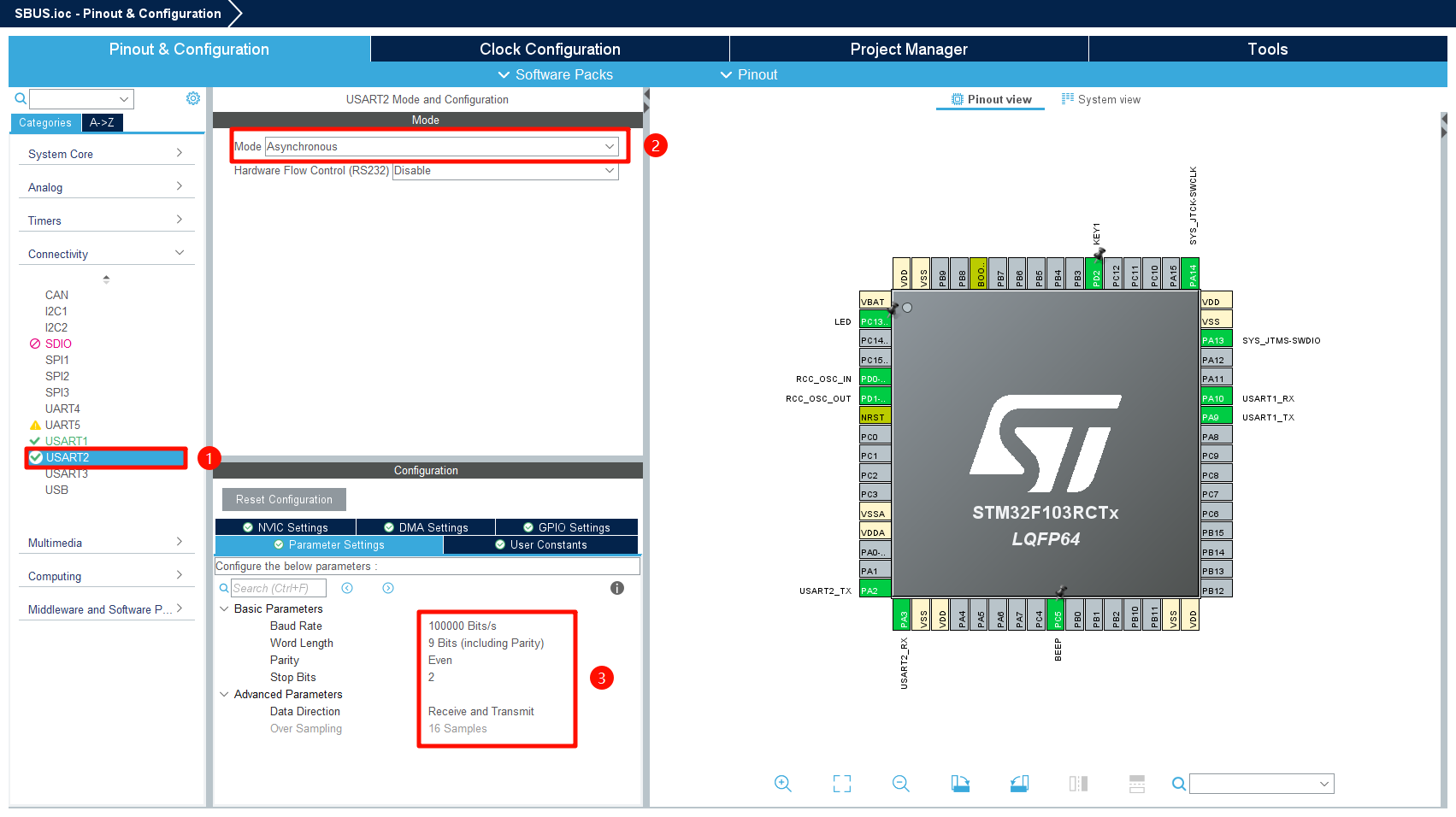
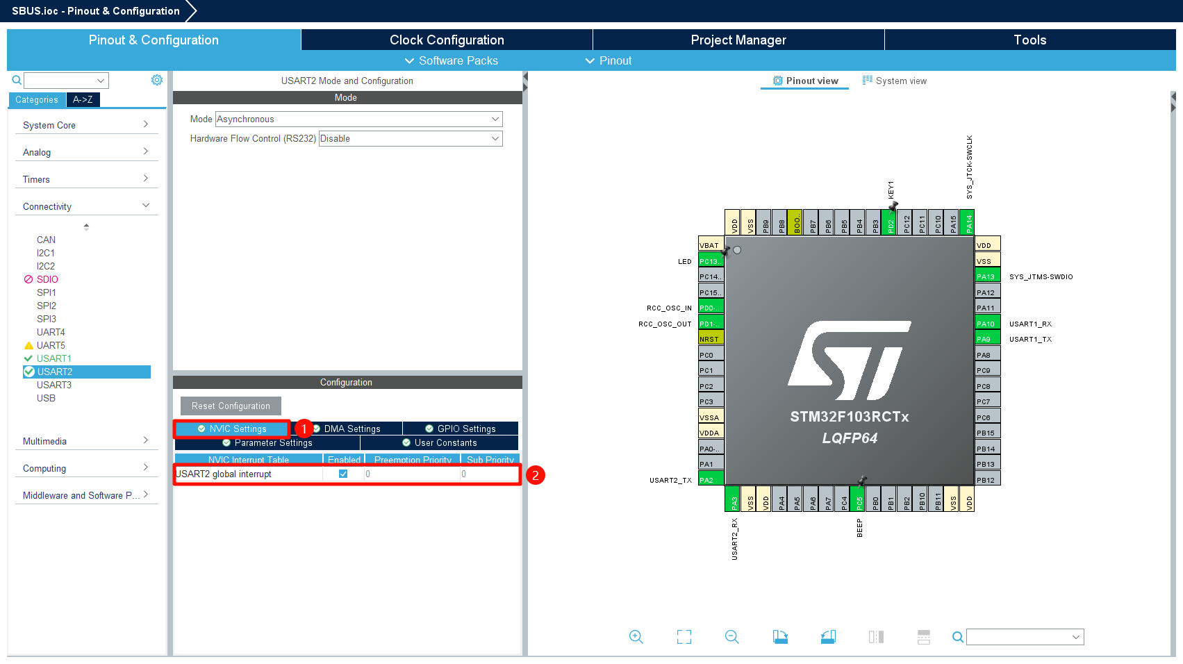
Project pin configuration
USART2
Mode:Asynchrinous
Basic Parameters:
Baud Rate:100000
Word Length:9
Parity:Even
Stop Bits:2
Data Direction:Receive and Transmit
Enable NVIC:USART2 global interrupt
Implementation principle
Serial port 2 receives the data of each channel sent by the SBUS receiver and parses it, and prints the correct data through serial port 1.
Core code
Serial port function
Serial port initialization
x// Initialize USARTvoid USART_Init(void){HAL_UART_Receive_IT(&huart1, (uint8_t *)&RxTemp, 1);HAL_UART_Receive_IT(&huart2, (uint8_t *)&RxTemp_2, 1);printf("start serial\n");}
Serial port interrupt receiving data
xxxxxxxxxx// The serial port receiving is interrupted. Procedurevoid HAL_UART_RxCpltCallback(UART_HandleTypeDef *huart){if (huart == &huart1){// Test sending data. In practice, data should not be sent during interruptsUSART1_Send_U8(RxTemp);// Continue receiving dataHAL_UART_Receive_IT(&huart1, (uint8_t *)&RxTemp, 1);}if (huart == &huart2){SBUS_Reveive(RxTemp_2);// printf("a:%d\n", RxTemp_2);HAL_UART_Receive_IT(&huart2, (uint8_t *)&RxTemp_2, 1);}}
SBUS data
Receive SBUS data
xxxxxxxxxx// Receives SBUS cache datavoid SBUS_Reveive(uint8_t data){// If the protocol start flag is met, data is receivedif (sbus_start == 0 && data == SBUS_START){sbus_start = 1;sbus_new_cmd = 0;sbus_buf_index = 0;inBuffer[sbus_buf_index] = data;inBuffer[SBUS_RECV_MAX - 1] = 0xff;}else if (sbus_start){sbus_buf_index++;inBuffer[sbus_buf_index] = data;}// Finish receiving a frame of dataif (sbus_start & (sbus_buf_index >= (SBUS_RECV_MAX - 1))){sbus_start = 0;if (inBuffer[SBUS_RECV_MAX - 1] == SBUS_END){memcpy(sbus_data, inBuffer, SBUS_RECV_MAX);sbus_new_cmd = 1;}}}
Parsing SBUS data
xxxxxxxxxx// Parses SBUS data into channel valuesstatic int SBUS_Parse_Data(void){g_sbus_channels[0] = ((sbus_data[1] | sbus_data[2] << 8) & 0x07FF);g_sbus_channels[1] = ((sbus_data[2] >> 3 | sbus_data[3] << 5) & 0x07FF);g_sbus_channels[2] = ((sbus_data[3] >> 6 | sbus_data[4] << 2 | sbus_data[5] << 10) & 0x07FF);g_sbus_channels[3] = ((sbus_data[5] >> 1 | sbus_data[6] << 7) & 0x07FF);g_sbus_channels[4] = ((sbus_data[6] >> 4 | sbus_data[7] << 4) & 0x07FF);g_sbus_channels[5] = ((sbus_data[7] >> 7 | sbus_data[8] << 1 | sbus_data[9] << 9) & 0x07FF);g_sbus_channels[6] = ((sbus_data[9] >> 2 | sbus_data[10] << 6) & 0x07FF);g_sbus_channels[7] = ((sbus_data[10] >> 5 | sbus_data[11] << 3) & 0x07FF);g_sbus_channels[8] = ((sbus_data[12] | sbus_data[13] << 8) & 0x07FF);g_sbus_channels[9] = ((sbus_data[13] >> 3 | sbus_data[14] << 5) & 0x07FF);#ifdef ALL_CHANNELSg_sbus_channels[10] = ((sbus_data[14] >> 6 | sbus_data[15] << 2 | sbus_data[16] << 10) & 0x07FF);g_sbus_channels[11] = ((sbus_data[16] >> 1 | sbus_data[17] << 7) & 0x07FF);g_sbus_channels[12] = ((sbus_data[17] >> 4 | sbus_data[18] << 4) & 0x07FF);g_sbus_channels[13] = ((sbus_data[18] >> 7 | sbus_data[19] << 1 | sbus_data[20] << 9) & 0x07FF);g_sbus_channels[14] = ((sbus_data[20] >> 2 | sbus_data[21] << 6) & 0x07FF);g_sbus_channels[15] = ((sbus_data[21] >> 5 | sbus_data[22] << 3) & 0x07FF);#endif// Security detection to check for lost connections or data errorsfailsafe_status = SBUS_SIGNAL_OK;if (sbus_data[23] & (1 << 2)){failsafe_status = SBUS_SIGNAL_LOST;printf("SBUS_SIGNAL_LOST\n");// lost contact errors}else if (sbus_data[23] & (1 << 3)){failsafe_status = SBUS_SIGNAL_FAILSAFE;printf("SBUS_SIGNAL_FAILSAFE\n");// data loss error}return failsafe_status;}
Print SBUS data
xxxxxxxxxxvoid SBUS_Handle(void){if (sbus_new_cmd){int res = SBUS_Parse_Data();sbus_new_cmd = 0;if (res) return;#if SBUS_ALL_CHANNELSprintf("%d,%d,%d,%d,%d,%d,%d,%d,%d,%d,%d,%d,%d,%d,%d,%d\r\n",g_sbus_channels[0], g_sbus_channels[1], g_sbus_channels[2],g_sbus_channels[3], g_sbus_channels[4], g_sbus_channels[5],g_sbus_channels[6], g_sbus_channels[7], g_sbus_channels[8],g_sbus_channels[9], g_sbus_channels[10], g_sbus_channels[11],g_sbus_channels[12], g_sbus_channels[13], g_sbus_channels[14],g_sbus_channels[15]);#elseprintf("%d,%d,%d,%d,%d,%d,%d,%d,%d,%d\r\n",g_sbus_channels[0], g_sbus_channels[1], g_sbus_channels[2],g_sbus_channels[3], g_sbus_channels[4],g_sbus_channels[5],g_sbus_channels[6], g_sbus_channels[7],g_sbus_channels[8],g_sbus_channels[9]);#endif}}
Main function
xxxxxxxxxxvoid Bsp_Loop(void){// Detect button down eventsif (Key1_State(KEY_MODE_ONE_TIME)){Beep_On_Time(50);static int press = 0;press++;printf("press:%d\n", press);}SBUS_Handle();Bsp_Led_Show_State_Handle();// The buzzer automatically shuts down when times outBeep_Timeout_Close_Handle();HAL_Delay(10);}
Hardware connection
| SBUS receiver | ROS control board |
|---|---|
| S | S |
| + | V |
| - | G |
Download program
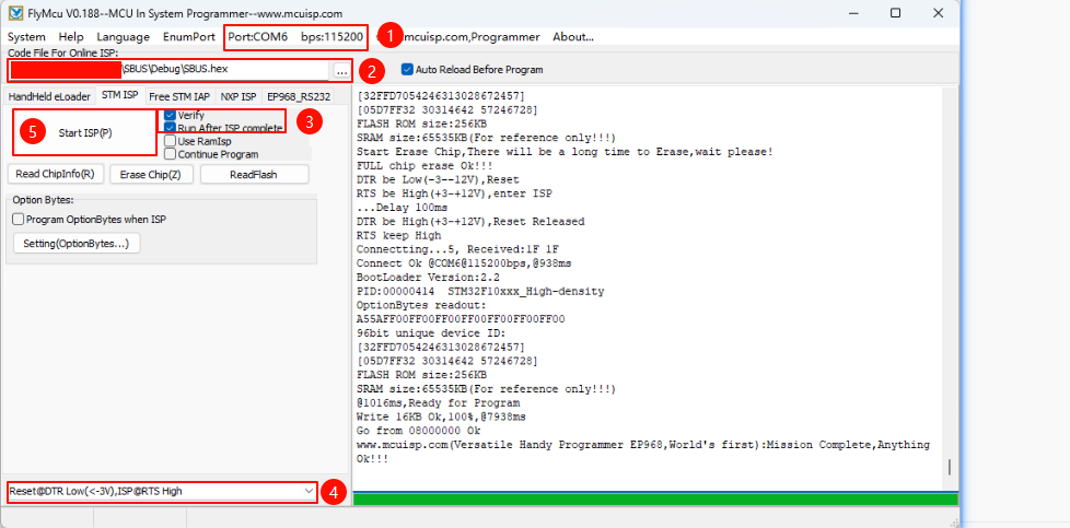
Use FlyMcu program to download the program: Different development boards have different ways to enter the download program mode. The ROS control board needs to press the BOOT button before powering on and release it after connecting to the computer
①: Serial port number and baud rate settings → The serial port number can be viewed in the system device manager, and the baud rate is 115200
②: Program file → Select the .hex file of the SBUS project: located in the Debug folder of the SBUS project
③④: Select according to the content in the picture
⑤: Confirm that all options are set correctly and click the burn option
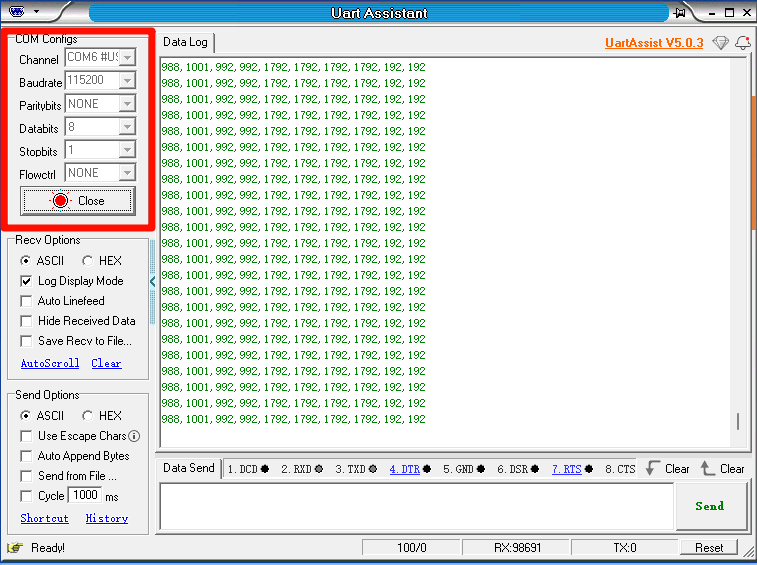
Experimental phenomenon
After downloading the SBUS file of the project to the ROS control board, the LED flashes every 200 milliseconds. We can connect the computer through the MicroUSB interface of the ROS control board and view the data of each channel of the HT-10A remote control through the serial port.
Note: The serial port option settings are set according to the figure below!
xxxxxxxxxxFor pairing the SBUS receiver with the HT-10A remote control, please refer to the [2. SBUS receiver pairing] tutorial, which contains the button descriptions for each channel of the HT-10A remote control