24-channel servo driver board
1. Learning objectives
Drive 180-degree servos through the serial port of the 24-channel servo driver board
2. Hardware connection
The servo used in this case is a 180-degree servo, which is connected to the S1 pin of the 16-channel servo driver board
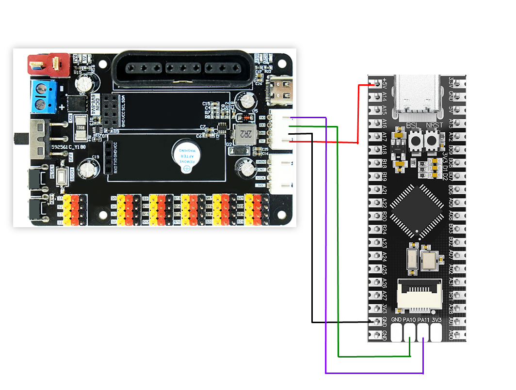
24-channel servo driver board and MSPM0G3507 wiring
3. Program description
- usart.h
x#ifndef __USART_H__#define __USART_H__#include "ti_msp_dl_config.h"void USART_Init(void);void USART_SendData(unsigned char data);#endif
Header file that defines serial port transmission data
- usart.c
xxxxxxxxxx#include "usart.h"#include "stdio.h"#define RE_0_BUFF_LEN_MAX 128volatile uint8_t recv0_buff[RE_0_BUFF_LEN_MAX] = {0};volatile uint16_t recv0_length = 0;volatile uint8_t recv0_flag = 0;void USART_Init(void){// SYSCFG初始化// SYSCFG initializationSYSCFG_DL_init();//清除串口中断标志//Clear the serial port interrupt flagNVIC_ClearPendingIRQ(UART_0_INST_INT_IRQN);//使能串口中断//Enable serial port interruptNVIC_EnableIRQ(UART_0_INST_INT_IRQN);}//串口发送一个字节//The serial port sends a bytestatic void USART_SendData(unsigned char data){//当串口0忙的时候等待//Wait when serial port 0 is busywhile( DL_UART_isBusy(UART_0_INST) == true );//发送//sendDL_UART_Main_transmitData(UART_0_INST, data);}//串口的中断服务函数//Serial port interrupt service functionvoid UART_0_INST_IRQHandler(void){uint8_t receivedData = 0;//如果产生了串口中断//If a serial port interrupt occursswitch( DL_UART_getPendingInterrupt(UART_0_INST) ){case DL_UART_IIDX_RX://如果是接收中断 If it is a receive interrupt// 接收发送过来的数据保存 Receive and save the data sentreceivedData = DL_UART_Main_receiveData(UART_0_INST);// 检查缓冲区是否已满 Check if the buffer is fullif (recv0_length < RE_0_BUFF_LEN_MAX - 1){recv0_buff[recv0_length++] = receivedData;}else{recv0_length = 0;}// 标记接收标志 Mark receiving flagrecv0_flag = 1;break;default://其他的串口中断 Other serial port interruptsbreak;}}
Define the serial port initialization function, the function to send one byte of data, and the serial port interrupt service function.
- empty.c
xxxxxxxxxxvoid UART_Servo(unsigned char servonum,unsigned char angle){servonum = 64 + servonum;date1 = angle/100 + 48;date2 = (angle%100)/10 + 48;date3 = angle%10 + 48;USART_SendData(0x24);//发送包头 Sending packet headerUSART_SendData(servonum);//发送舵机编号 Send servo numberUSART_SendData(date1);//发送角度 Send angleUSART_SendData(date2);//发送角度 Send angleUSART_SendData(date3);//发送角度 Send angleUSART_SendData(0x23);//发送包尾 Send packet taildelay_ms(100);}int main(void){USART_Init();while (1){for(i = 0;i<180;i+=5){UART_Servo(1,i);if(i>180) i=0;}}}
Define the serial port control function UART_Servo, where the parameter servonum has a value range of (1-24) and angle has a value range of (0-270). In the main function, assign values to the serial port control function. Use loops to achieve 0-180 value changes.
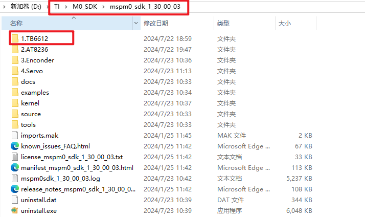
Note: The project source code must be placed in the SDK path for compilation,
For example, the path: D:\TI\M0_SDK\mspm0_sdk_1_30_00_03\1.TB6612
4. Experimental phenomenon
Connect the servo to the S1 interface of the 24-way servo driver board, and burn the program to MSPM0G3507. After burning, connect the MSPM0G3507 to the 24-way servo driver board according to the wiring diagram. After power on, you will see the servo rotate from 0-180 degrees. Finally, it returns to 0 degrees.