Basic timer
Basic timerHardware connectionControl principleSoftware configurationSoftware codeControl functionExperimental phenomenon
The tutorial demonstrates how to use the basic timer (TIM6) to control the onboard LED on the development board to flash.
The tutorial only introduces the standard library project code
Hardware connection
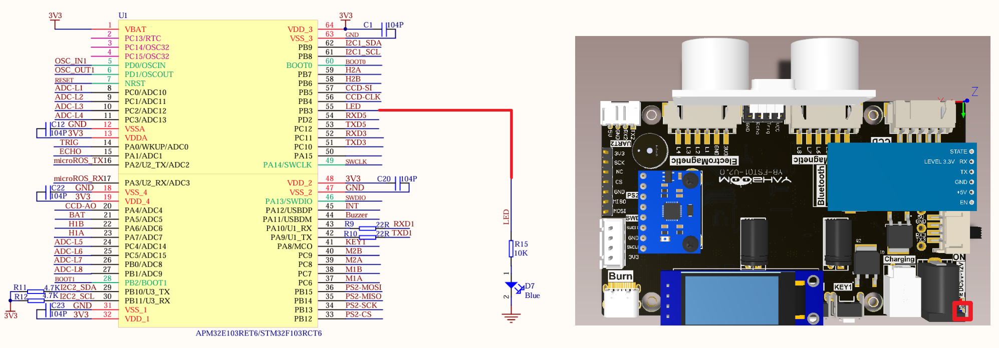
| Peripherals | Development board | Description |
|---|---|---|
| LED | PB3 | The anode of the LED is connected to the development board PB3, and the cathode is connected to the development board GND |
Control principle
Use the timing function of TIM6 on the STM32F103RCT6 development board
Use the GPIO output function to control the LED and implement the timing function through the basic timer.
Basic timer
Use the timing function of TIM6 on the STM32F103ZET6 development board
| Timer type | Basic timer |
|---|---|
| Timer name | TIM6, TIM7 |
| Counter bit number | 16 |
| Counting mode | Incrementing |
| Prescaler coefficient | 1-65536 |
| Generate DMA request | Yes |
| Capture/compare channel | 0 |
| Complementary output | None |
| Clock frequency | 72MHz (maximum) |
| Mount bus | APB1 |
Time base unit
| Register | Function |
|---|---|
| Counter register (TIMx_CNT) | Current count value of the counter |
| Prescaler register (TIMx_PSC) | Set the scaler coefficient (1-65536) |
| Auto-reload register (TIMx_ARR) | Counter count boundary and reload value |
Timing formula
| Parameter | Meaning |
|---|---|
| T(s) | Timing time, in seconds |
| ARR | Auto-reload value |
| PSC | Prescaler coefficient |
| TIM_CLK | Timer clock, in Hz |
Timing time for this project: 10ms
Software configuration
Software code
Configure the timing function of the basic timer TIM6, without configuring specific pins.
xxxxxxxxxxProduct supporting materials source code path: Attachment → Source code summary → 1.Base_Course → 7.Base_Time
Control function
The tutorial only briefly introduces the code, you can open the project source code to read it.
TIM6_Init
xvoid TIM6_Init(void){TIM_TimeBaseInitTypeDef TIM_TimeBaseStructure;NVIC_InitTypeDef NVIC_InitStructure;RCC_APB1PeriphClockCmd(RCC_APB1Periph_TIM6, ENABLE); //Enable the timer clockTIM_TimeBaseStructure.TIM_Prescaler = 7199; //PrescalerTIM_TimeBaseStructure.TIM_Period = 99; //Set the counter auto-reload valueTIM_TimeBaseInit(TIM6, &TIM_TimeBaseStructure);TIM_ClearFlag(TIM6, TIM_FLAG_Update); //Clear the update flag of TIMTIM_ITConfig(TIM6, TIM_IT_Update, ENABLE);//Interrupt priority NVIC settingsNVIC_InitStructure.NVIC_IRQChannel = TIM6_IRQn; //TIM6 interruptNVIC_InitStructure.NVIC_IRQChannelPreemptionPriority = 4; //Preempt priority level 4NVIC_InitStructure.NVIC_IRQChannelSubPriority = 2; //From priority level 2NVIC_InitStructure.NVIC_IRQChannelCmd = ENABLE; //IRQ channel is enabledNVIC_Init(&NVIC_InitStructure); //Initialize NVIC registersTIM_Cmd(TIM6, ENABLE);}
TIM6_IRQHandler
xxxxxxxxxxvoid TIM6_IRQHandler(void){if (TIM_GetITStatus(TIM6, TIM_IT_Update) != RESET) //Check whether TIM update interrupt occurs{TIM_ClearITPendingBit(TIM6, TIM_IT_Update); //Clear TIMx update interrupt flagled_count++; //LED service display flagcotrol_led();//Light service 3 seconds within the light flash 3 times}}
cotrol_led
xxxxxxxxxxvoid cotrol_led(void){if(!led_flag){if(led_count>300)//3S{led_count = 0;led_flag = 1;}}else{if(led_count>20)//200ms{led_count = 0;LED = !LED;//State inversionled_twinkle_count++;if(led_twinkle_count == 6){LED = 0;led_twinkle_count = 0;led_flag = 0;}}}
Experimental phenomenon
The Base_Time.hex file generated by the project compilation is located in the OBJ folder of the Base_Time project. Find the Base_Time.hex file corresponding to the project and use the FlyMcu software to download the program into the development board.
After the program is successfully downloaded: the LED flashes three times every 3 seconds.