DMA:USART
DMA:USARTHardware connectionControl principlePin definitionSoftware codeControl functionExperimental phenomenon
The tutorial demonstrates serial port (USART1) communication via DMA.
The tutorial only introduces the standard library project code
Hardware connection
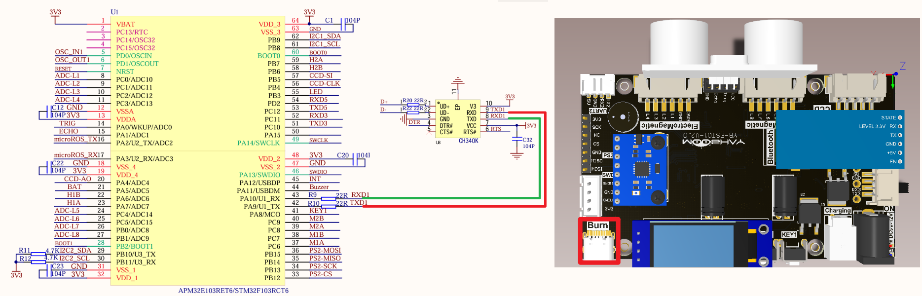
| Peripherals | Development board | Description |
|---|---|---|
| USART1_TX | PA9 | USART1 sends data |
| USART1_RX | PA10 | USART1 receives data |
Control principle
xxxxxxxxxxSerial port related knowledge will not be introduced, mainly DMA knowledge.
STM32F103RCT6 has two DMA controllers, DMA1 has 7 channels and DMA2 has 5 channels;
It is used for high-speed data transmission between peripherals and memory and between memory and memory.
DMA features
DMA initialization and startup are completed by the CPU, and the transfer process is performed by the DMA controller without CPU involvement, thus saving CPU resources for other operations.
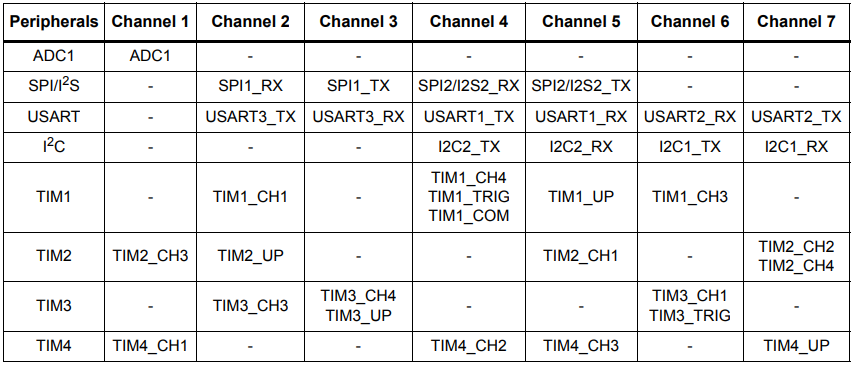
DMA1 requests for each channel
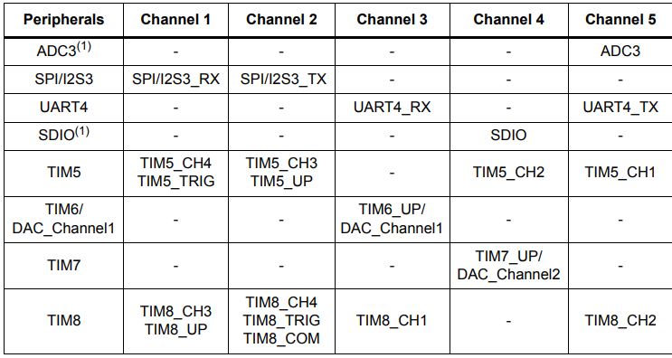
DMA2 requests for each channel
This tutorial uses DMA1 channel 4.
Pin definition
| Main control chip | Pin | Main function (after reset) | Default multiplexing function | Redefine function |
|---|---|---|---|---|
| STM32F103RCT6 | PA9 | PA9 | USART1_TX/TIM1_CH2 | |
| STM32F103RCT6 | PA10 | PA10 | USART1_RX/TIM1_CH3 |
Software code
Since the default function of the PA9/10 pin is a normal IO pin function, we need to use the multiplexing function.
xxxxxxxxxxProduct supporting data source code path: Attachment → Source code summary → 1.Base_Course → 15.USART+DMA
Control function
The tutorial only briefly introduces the code, and you can open the project source code to read it in detail.
uart_init
xvoid uart_init(u32 bound){//GPIO port settingsGPIO_InitTypeDef GPIO_InitStructure;USART_InitTypeDef USART_InitStructure;NVIC_InitTypeDef NVIC_InitStructure;RCC_APB2PeriphClockCmd(RCC_APB2Periph_USART1|RCC_APB2Periph_GPIOA, ENABLE); //Enable USART1, GPIOA clock//USART1_TX GPIOA.9GPIO_InitStructure.GPIO_Pin = GPIO_Pin_9; //PA.9GPIO_InitStructure.GPIO_Speed ••= GPIO_Speed_50MHz;GPIO_InitStructure.GPIO_Mode = GPIO_Mode_AF_PP; //Multiplex push-pull outputGPIO_Init(GPIOA, &GPIO_InitStructure);//Initialize GPIOA.9//Initialize USART1_RX GPIOA.10GPIO_InitStructure.GPIO_Pin = GPIO_Pin_10;//PA10GPIO_InitStructure.GPIO_Mode = GPIO_Mode_IN_FLOATING;//Floating inputGPIO_Init(GPIOA, &GPIO_InitStructure);//Initialize GPIOA.10//USART initialization settingsUSART_InitStructure.USART_BaudRate = bound;//Serial port baud rateUSART_InitStructure.USART_WordLength = USART_WordLength_8b;//Word length is 8-bit data formatUSART_InitStructure.USART_StopBits = USART_StopBits_1;//One stop bitUSART_InitStructure.USART_Parity = USART_Parity_No; //No parity bitUSART_InitStructure.USART_HardwareFlowControl = USART_HardwareFlowControl_None; //No hardware data flow controlUSART_InitStructure.USART_Mode = USART_Mode_Rx | USART_Mode_Tx; //Transmit and receive modeUSART_Init(USART1, &USART_InitStructure); //Initialize serial port 1USART_ITConfig(USART1, USART_IT_RXNE, ENABLE); //Serial port receive interruptUSART_Cmd(USART1, ENABLE); //Enable serial port 1NVIC_InitStructure.NVIC_IRQChannel = USART1_IRQn;NVIC_InitStructure.NVIC_IRQChannelPreemptionPriority = 0;NVIC_InitStructure.NVIC_IRQChannelSubPriority = 1; NVIC_InitStructure.NVIC_IRQChannelCmd = ENABLE;NVIC_Init(&NVIC_InitStructure);}
USARTx_DMA_Config
xxxxxxxxxxvoid USARTx_DMA_Config(void){DMA_InitTypeDef DMA_InitStructure;// Enable serial port DMA clockRCC_AHBPeriphClockCmd(USART_TX_DMA_CLK, ENABLE);// Set DMA source address: serial port data register address*/DMA_InitStructure.DMA_PeripheralBaseAddr = USART_DR_ADDRESS;// Memory address (pointer to the variable to be transferred)DMA_InitStructure.DMA_MemoryBaseAddr = (uint32_t)SendBuff;// Direction: from memory to peripheralsDMA_InitStructure.DMA_DIR = DMA_DIR_PeripheralDST;// Transfer sizeDMA_InitStructure.DMA_BufferSize = SENDBUFF_SIZE;// Peripheral address does not increaseDMA_InitStructure.DMA_PeripheralInc = DMA_PeripheralInc_Disable;// Memory address incrementDMA_InitStructure.DMA_MemoryInc = DMA_MemoryInc_Enable;// Peripheral data unitDMA_InitStructure.DMA_PeripheralDataSize =DMA_PeripheralDataSize_Byte;// Memory data unitDMA_InitStructure.DMA_MemoryDataSize = DMA_MemoryDataSize_Byte;// DMA mode, one-time or circular modeDMA_InitStructure.DMA_Mode = DMA_Mode_Normal;//DMA_InitStructure.DMA_Mode = DMA_Mode_Circular;// Priority: MediumDMA_InitStructure.DMA_Priority = DMA_Priority_Medium;// Disable memory-to-memory transferDMA_InitStructure.DMA_M2M = DMA_M2M_Disable;// Configure DMA channelDMA_Init(USART_TX_DMA_CHANNEL, &DMA_InitStructure);// Clear the conversion flag of DMA1 channel 4DMA_ClearFlag(USART_TX_DMA_FLAG_TC );// Enable DMADMA_Cmd (USART_TX_DMA_CHANNEL,ENABLE);}
Experimental phenomenon
The USART_DMA.hex file generated by the project compilation is located in the OBJ folder of the [USART+DMA] project. Find the USART_DMA.hex file corresponding to the project and use the FlyMcu software to download the program to the development board.
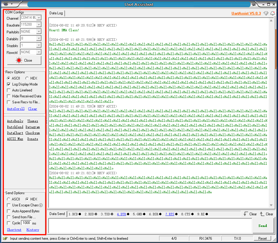
After the program is successfully downloaded: Use the serial port debugging assistant to view the information, and you can see that the serial port prints Usart1 DMA Class! and Hello (Hello prints for about 300ms).
xxxxxxxxxxWhen using the serial port debugging assistant, you need to pay attention to the serial port settings. If the settings are wrong, the phenomenon may be inconsistent