Ultrasonic module-measuring distance (TIM)
Ultrasonic module-measuring distance (TIM)Hardware connectionControl principlePin definitionSoftware codeControl functionExperimental phenomenon
The tutorial mainly demonstrates the implementation of the ultrasonic module distance measurement function.
GPIO general push-pull output function triggers the ultrasonic module distance measurement; timer input capture obtains the ultrasonic high level time, thereby calculating the obstacle distance.The tutorial only introduces the standard library project code
Hardware connection
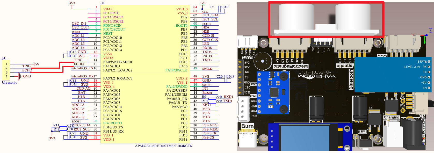
Just install it to the corresponding interface:
| Ultrasonic module | STM32F103RCT6 |
|---|---|
| VCC | 5V |
| TRIG | PA0 |
| ECHO | PA1 |
| GND | GND |
Control principle
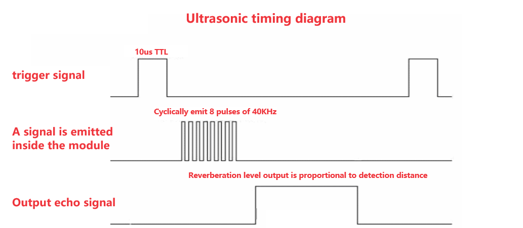
Trigger ranging signal
The TRIG pin sends a high level signal for more than 10us.
xxxxxxxxxxThe ultrasonic module will automatically send 8 40KHz square waves and automatically detect whether there is a signal return
Receive echo signal
If there is a signal return, the ECHO pin will output a high level. The duration of the high level is the time from the ultrasonic wave transmission to the return.
Distance conversion
xxxxxxxxxxT: Echo signal high level timeV: Sound speed (approximately equal to 340m/s)
Pin definition
| Main control chip | Pin | Main function (after reset) | Default multiplexing function | Redefine function |
|---|---|---|---|---|
| STM32F103RCT6 | PA0 | PA0 | WKUP/USART2_CTS/ADC123_IN0/TIM2_CH1_ETR/TIM5_CH1/TIM8_ETR | |
| STM32F103RCT6 | PA1 | PA1 | USART2_RTS/ADC123_IN1/TIM5_CH2/TIM2_CH2 |
Software code
Since the default function of all pins is the ordinary IO pin function, we need to use the multiplexing function.
xxxxxxxxxxProduct supporting materials source code path: Attachment → Source code summary → 2.Extended_Course → 2.Ultrasonic
Control function
The tutorial only briefly introduces the code, you can open the project source code to read it in detail.
ultrasonic_init
xstatic void ultrasonic_init(void){GPIO_InitTypeDef GPIO_InitStructure;RCC_APB2PeriphClockCmd(ULTRASONIC_RCC, ENABLE); // Enable the GPIOA clockGPIO_InitStructure.GPIO_Pin = ECHO_PIN;GPIO_InitStructure.GPIO_Mode = GPIO_Mode_IPD; //PA1 InputGPIO_InitStructure.GPIO_Speed = GPIO_Speed_50MHz; //50MGPIO_Init(ECHO_PORT, &GPIO_InitStructure);GPIO_InitStructure.GPIO_Pin = TRIG_PIN;GPIO_InitStructure.GPIO_Mode = GPIO_Mode_Out_PP; //PA3 outputGPIO_InitStructure.GPIO_Speed = GPIO_Speed_50MHz; //50MGPIO_Init(TRIG_PORT, &GPIO_InitStructure);}
TIM2_Cap_Init
xxxxxxxxxxvoid TIM2_Cap_Init(u16 arr,u16 psc){TIM_ICInitTypeDef TIM2_ICInitStructure;TIM_TimeBaseInitTypeDef TIM_TimeBaseStructure;NVIC_InitTypeDef NVIC_InitStructure;ultrasonic_init();RCC_APB1PeriphClockCmd(RCC_APB1Periph_TIM2, ENABLE); //Enable TIM2 clock//Initialize timer 2 TIM2TIM_TimeBaseStructure.TIM_Period = arr; //Set counter auto-reload valueTIM_TimeBaseStructure.TIM_Prescaler = psc; //PrescalerTIM_TimeBaseStructure.TIM_ClockDivision = TIM_CKD_DIV1; //Set clock division: TDTS = Tck_timTIM_TimeBaseStructure.TIM_CounterMode = TIM_CounterMode_Up; //TIM up counting modeTIM_TimeBaseInit(TIM2, &TIM_TimeBaseStructure); //Initialize the time base unit of TIMx according to the parameters specified in TIM_TimeBaseInitStruct//Initialize TIM2 input capture parametersTIM2_ICInitStructure.TIM_Channel = TIM_Channel_2; //CC1S=02 Select input IC2 to map to TI1TIM2_ICInitStructure.TIM_ICPolarity = TIM_ICPolarity_Rising; //Rising edge captureTIM2_ICInitStructure.TIM_ICSelection = TIM_ICSelection_DirectTI;TIM2_ICInitStructure.TIM_ICPrescaler = TIM_ICPSC_DIV1; //Configure input frequency division, no frequency divisionTIM2_ICInitStructure.TIM_ICFilter = 0x00; //Configure input filter No filteringTIM_ICInit(TIM2, &TIM2_ICInitStructure);//Interrupt group initializationNVIC_InitStructure.NVIC_IRQChannel = TIM2_IRQn; //TIM2 interruptNVIC_InitStructure.NVIC_IRQChannelPreemptionPriority = 1; //Preempt priority level 1NVIC_InitStructure.NVIC_IRQChannelSubPriority = 1; //From priority level 1NVIC_InitStructure.NVIC_IRQChannelCmd = ENABLE; //IRQ channel is enabledNVIC_Init(&NVIC_InitStructure); //Initialize peripheral NVIC registers according to the parameters specified in NVIC_InitStructTIM_ITConfig(TIM2,TIM_IT_Update|TIM_IT_CC2,ENABLE);//Allow update interrupts, allow CC2IE to capture interruptsTIM_Cmd(TIM2,ENABLE); //Enable timer 2}
TIM2_IRQHandler
xxxxxxxxxxvoid TIM2_IRQHandler(void){u16 tsr;tsr=TIM2->SR;if((TIM2CH2_CAPTURE_STA&0X80)==0)// Capture has not succeeded{if(tsr&0X01)// The timer overflows{if(TIM2CH2_CAPTURE_STA&0X40)// The high level has been captured{if((TIM2CH2_CAPTURE_STA&0X3F)==0X3F)// The high level is too long{TIM2CH2_CAPTURE_STA|=0X80; // Indicates a successful captureTIM2CH2_CAPTURE_VAL=0XFFFF;}else TIM2CH2_CAPTURE_STA++;}}if(tsr&0x04)// Capture 2 A capture event occurred{if(TIM2CH2_CAPTURE_STA&0X40) // Captures a falling edge{TIM2CH2_CAPTURE_STA|=0X80; // Mark that a high level pulse width was successfully capturedTIM2CH2_CAPTURE_VAL=TIM2->CCR2; // Gets the current capture value.TIM2->CCER&=~(1<<5); //CC2P=0 Set to rising edge capture}else // Not yet started, first capture rising edge{TIM2CH2_CAPTURE_STA=0; // EmptyTIM2CH2_CAPTURE_VAL=0;TIM2CH2_CAPTURE_STA|=0X40; // The flag captures the rising edgeTIM2->CNT=0; // The counter is clearedTIM2->CCER|=1<<5; //CC2P=1 Set to falling edge capture}}}TIM2->SR=0; // Clears the interrupt flag bit}
Experimental phenomenon
The Ultrasonic.hex file generated by the project compilation is located in the OBJ folder of Ultrasonic project. The corresponding Ultrasonic.hex file is found and the program is downloaded into the development board by using FlyMcu software.
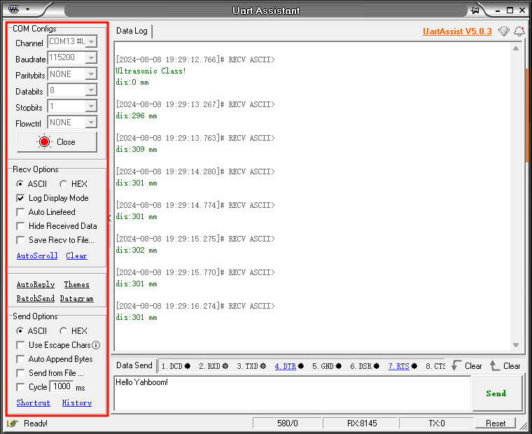
After successful download: Serial port will print Ultrasonic Class! After hardware initialization Then control LED status switch and print obstacle distance every 500ms.
xxxxxxxxxxWhen using the serial port debugging Assistant, pay attention to the serial port Settings. Incorrect Settings may cause inconsistency