Motor introduction and usage
This course is used to explain the parameters of the motor, the recommended supply voltage, and the recommended wiring method for connecting the motor to the 4-channel motor driver board.
Motor introduction and usage1. 520 motor2. 310 motor3. DC TT Motor4. TT motor with encoder speed measurement5. L-type 520 motor
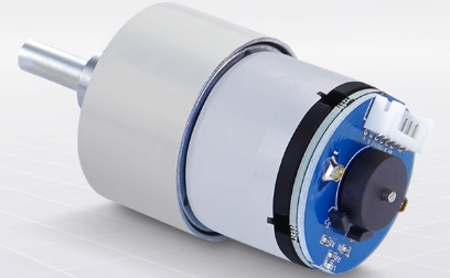
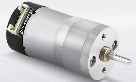
1. 520 motor
| Parameter | MD520Z19_12V | MD520Z30_12V | MD520Z56_12V |
|---|---|---|---|
| Rated voltage | 12V | 12V | 12V |
| Motor type | Permanent magnet brush | Permanent magnet brush | Permanent magnet brush |
| Output shaft | 6mm diameter D-type eccentric shaft | 6mm diameter D-type eccentric shaft | 6mm diameter D-type eccentric shaft |
| Stall torque | 3.1kg·cm | 4.8kg·cm | 8.3kg·cm |
| Rated torque | 2.2kg·cm | 3.3kg·cm | 6.5kg·cm |
| Speed before deceleration | 11000rpm | 11000rpm | 12000rpm |
| Speed after deceleration | 550±10rpm | 333±10rpm | 205±10rpm |
| Rated power | ≤4W | ≤4W | ≤4W |
| Stall current | 3A | 3A | 4A |
| Rated current | 0.3A | 0.3A | 0.3A |
| Gear set reduction ratio | 1:19 | 1:30 | 1:56 |
| Encoder type | AB phase incremental Hall encoder | AB phase incremental Hall encoder | AB phase incremental Hall encoder |
| Encoder supply voltage | 3.3-5V | 3.3-5V | 3.3-5V |
| Magnetic loop number | 11 line | 11 line | 11 line |
| Interface type | PH2.0 6Pin | PH2.0 6Pin | PH2.0 6Pin |
| Function | With built-in pull-up shaping, the MCU can directly read the signal pulse | With built-in pull-up shaping, the MCU can directly read the signal pulse | With built-in pull-up shaping, the MCU can directly read the signal pulse |
| Single motor weight | 150g±1g | 150g±1g | 150g±1g |
Recommended power supply: 12V.
There are three types of 520 motors, and their rated voltage is 12V. When we drive the 520 motor, we can connect a voltage between 11 and 16V, and it is recommended to use a 12V voltage supply**.
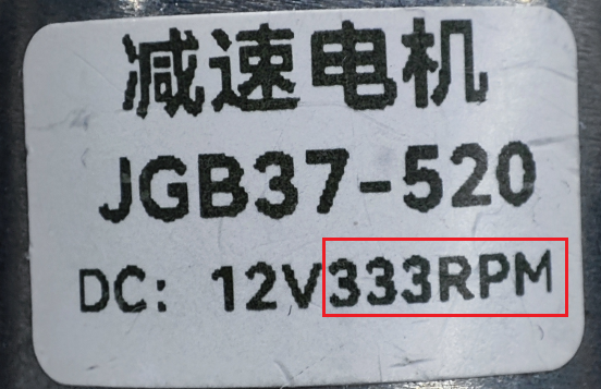
If you want to distinguish the model of the 520 motor you bought, you can directly look at the label printed on the 520 motor. There is a text printed on it called RPM, and the number in front of RPM corresponds to the speed after deceleration number in the parameter table.
For example, the label of the 520 motor in my hand says 333RPM, so you should pay attention to the parameters in the MD520Z30_12V column. In particular, the two parameters of reduction ratio and number of magnetic ring lines may be modified when using a 4-channel motor driver board.
Recommended wiring:
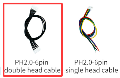
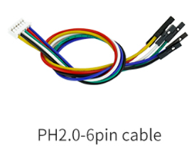
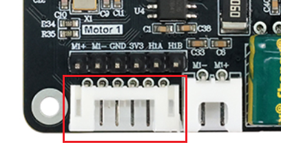
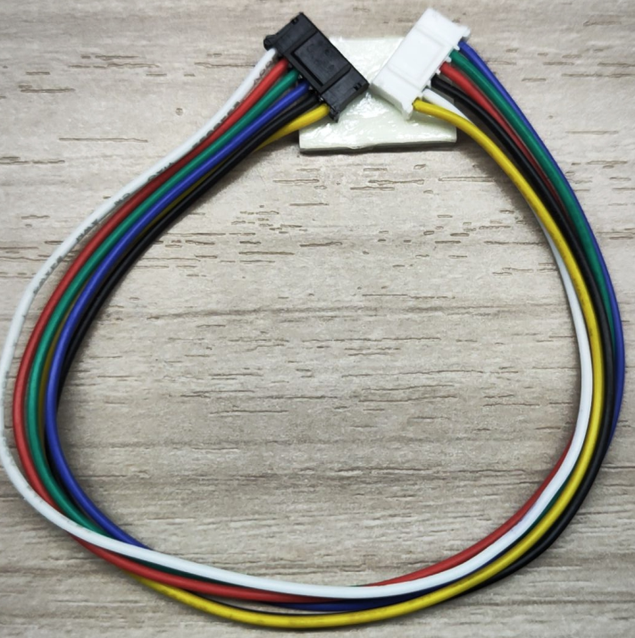
The 520 motor you purchased will come with two types of cables. Here we recommend that you choose the black PH2.0-6PIN double-ended cable, one end connected to the motor, and the other end directly connected to the PH2.0-6PIN encoder motor interface on the four-way motor driver board. We can find that the A on the motor corresponds to the B phase of the four-way motor driver board.
So when configuring the motor type on the four-way motor driver board, you should choose $mtype:1#, the model of the 520 motor.

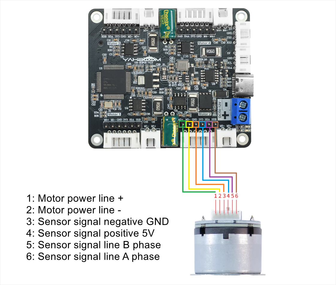
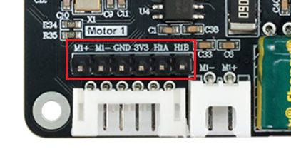
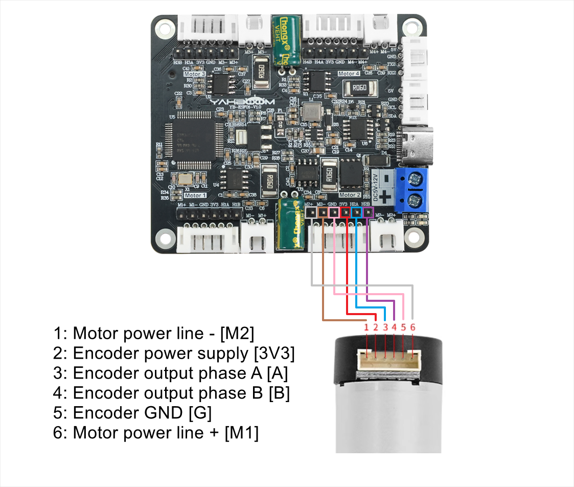
520 motor wiring instructions:
If you use PH2.0-6PIN to Dupont line connection, you can connect according to the picture below. With this connection, the motor phase A will be connected to the four-way motor driver board phase A, and phase B will be connected to phase B.
However, when configuring the motor type, you should select $mtype:2#, the model of the 310 motor.
2. 310 motor
| Parameter | Value/description |
|---|---|
| Motor name | MD310Z20_7.4V |
| Stall current | ≤1.4A |
| Motor rated voltage | 7.4V |
| Rated current | ≤0.65A |
| Motor type | Permanent magnet brush |
| Gear set reduction ratio | 1:20 |
| Output shaft | 3mm diameter D-type eccentric shaft |
| Encoder type | AB phase incremental Hall encoder |
| Stall torque | ≥1.0kg·cm |
| Encoder supply voltage | 3.3-5V |
| Rated torque | 0.4kg·cm |
| Magnetic loop number | 13 line |
| Speed before deceleration | 9000rpm |
| Interface type | PH2.0 6Pin |
| Functions | With built-in pull-up shaping, the MCU can directly read the signal pulse |
| Speed after deceleration | 450±10rpm |
| Rated power | 4.8W |
| Single motor weight | 70g |
Recommended power supply: 7.4V. It can be connected to a voltage between 4.2~8.4V, recommended to use a voltage of 7.4V.
The two parameters reduction ratio and number of magnetic ring lines in the main parameter table are required. These two parameters may be modified when using a four-way motor driver board.
If you buy a 310 motor alone, you will receive a PH2.0-6PIN to DuPont cable. When connecting a 4-channel driver board, connect it to its IO socket.
310 motor wiring instructions:
When the A phase of the 310 motor is connected to the A phase of the 4-channel motor driver board, and the B phase is connected to the B phase, then when configuring the motor type, you should select $mtype:2#, the model of the 310 motor.
If you purchased the 310 motor in the chassis kit, it has a PH2.0-6PIN double-ended cable. You can connect the black end to the 310 motor and the white end to the PH2.0-6PIN encoder motor interface on the 4-channel motor driver board.
At this time, select $mtype:2# to configure the motor type, which is the model of the 310 motor.

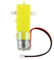
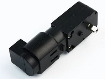
3. DC TT Motor
| Parameter | Value/Description |
|---|---|
| Model | TT gear motor |
| Brush material | Carbon brush |
| Reduction ratio | 1:48 |
| Rated voltage | 6V |
| Idle current | 200MA |
| Stall current | 1.5A |
| Torque | 0.8N.m |
| Speed before deceleration | 12000±10%rpm |
| Speed after deceleration | 245±10%rpm |
Recommended power supply: 7.4V
This motor has no encoder, so you only need to modify motor type and reduction ratio in the four-way motor driver board. When configuring the motor type, select $mtype:4#, the TT motor model without encoder.
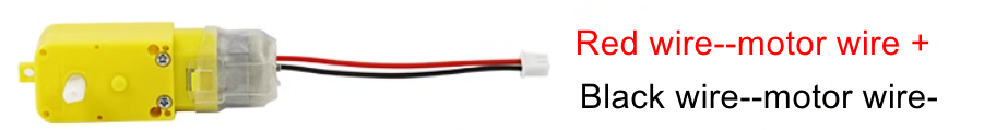
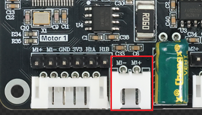
Recommended wiring: Connect the XH2.54-2PIN interface on the TT motor directly to the XH2.54-2PIN socket on the 4-channel motor driver board.
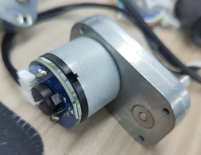
4. TT motor with encoder speed measurement
| Parameter | Value/Description |
|---|---|
| Model | 13-wire metal single-axis TT motor |
| Motor type | 130 Motor |
| Motor type/brush material | Copper brush |
| Reduction ratio | 1:45 |
| Rated voltage | 6V |
| No-load current | 0.08A |
| Rated current | 0.3A |
| Stall current | 1.1A |
| Torque | 1.2N.m |
| Speed before deceleration | 16000±5%rpm |
| Speed after deceleration | 355±5%rpm |
| Encoder type | Hall AB phase encoder |
| Encoder power supply | 3.3-5V |
| Encoder line number | 13 line |
| Maximum count per wheel revolution | 2340 |
| Features | With built-in pull-up shaping, the MCU can read directly |
Recommended power supply: 7.4V. It can be connected to 5~13V, recommended to use 7.4V voltage power supply.
The two parameters reduction ratio and encoder line number in the main parameter table are required. These two parameters may be modified when using the 4-channel motor driver board.
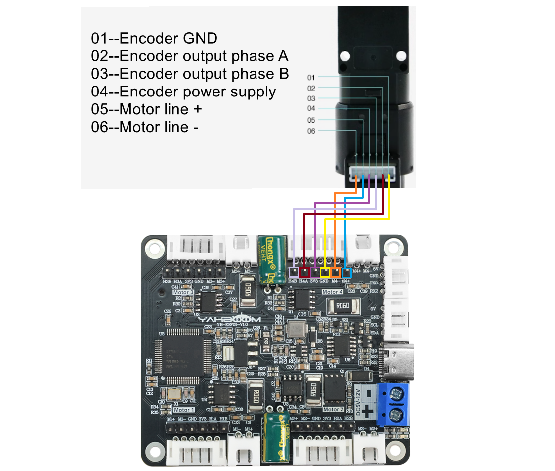
Recommended wiring: Use the PH2.0-6PIN to DuPont line cable and connect it to the IO socket of the 4-channel motor driver board.
Wiring instructions for encoder speed measurement TT motor:
When the A phase of the encoder TT motor is connected to the A phase of the four-way motor driver board, and the B phase is connected to the B phase, then when configuring the motor type, you should select $mtype:3#, the model of the TT motor with encoder.
5. L-type 520 motor
| Parameter | Value/Description |
|---|---|
| Model | L-type 520 motor |
| Starting voltage | 6V |
| Rated voltage | 12V |
| Reduction ratio | 1:40 |
| Magnetic loop number | 11线 |
| No-load current | ≥450mA |
| No-load speed | 300r/min±5% |
| Rated torque | 4.4KG.CM |
| Rated speed | 150r/min |
| Stall torque | 10KG.CM |
| Stall current | 4A |
Recommended power supply: 12V.
The two parameters reduction ratio and encoder line number in the main parameter table are required. These two parameters may be modified when using the 4-channel motor driver board.
Recommended wiring: The purchased L-type 520 motor will come with two types of wires. Here we recommend that you choose the black PH2.0-6PIN double-headed cable, one end is connected to the motor, and the other end is directly connected to the PH2.0-6PIN encoder motor interface on the 4-channel motor driver board.
This wiring is the most convenient, but it can be found that the A on the motor corresponds to the B phase of the 4-channel motor driver board. Therefore, when configuring the motor type on the 4-channel motor driver board, you should choose $mtype:1#, the model of the 520 motor.
L-type 520 motor wiring instructions:
If you use PH2.0-6PIN to Dupont line connection, you can connect according to the picture below. With this connection, the motor's A phase will be connected to the 4-channel motor driver board A phase, and B phase will be connected to B phase.
However, when configuring the motor type, you should select $mtype:2#, the model of the 310 motor.