Servo control
Servo control1. Software-Hardware2. Brief principle1. Hardware schematic diagram2. Physical connection diagram3. Control principle3. Engineering experience1. Open the project4. Project configuration1. New project2、chip selection3、Project settings4、Pin configuration5、Clock configuration6、Project configuration7、Generate code5. Main functions1. User function2. HAL library function analysis6. Program download1. Serial port download2、ST-Link Download7. Experimental Phenomenon
This tutorial demonstrates: using the basic timer (TIM7) interrupt to simulate PWM control of the external S1 interface servo on the development board.
The first tutorial in this chapter will be more detailed than the following tutorials. The purpose is to demonstrate from the new project to the complete effect, and guide users how to use STM32CubeIDE to develop
1. Software-Hardware
STM32F103CubeIDE
STM32 Robot Development Board
180° servo
Type-C data cable or ST-Link
Download programs or simulate the development board
2. Brief principle
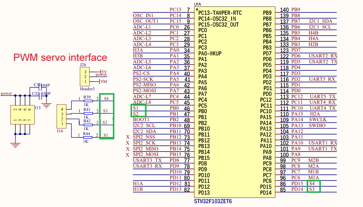
1. Hardware schematic diagram
2. Physical connection diagram

Note: Refer to the color of the servo wire for servo wiring. This experiment requires connecting 5V and GND jumper caps
| Steering gear | Development board |
|---|---|
| VCC(red) | 5V |
| SIG(yellow) | S1/S2/S3/S4 |
| GND(brown) | GND |
3. Control principle
By changing the duty cycle of the PWM signal, the angle of rotation of the servo is controlled
- PWM(Pulse Width Modulation)
PWM is the abbreviation of pulse width modulation, which is a technology that controls the level by adjusting the pulse width of the signal.
Period: The duration of a complete PWM waveform;
Duty cycle: the ratio of high level duration to cycle time;
Frequency: The reciprocal of the period is called frequency, which is the number of PWM cycles generated per second;
PWM servo
Set the period of the PWM control signal to 20ms, which is a frequency of 50Hz; the high level time of the pulse determines the angle of rotation of the servo.
High level pulse width corresponding to common angles
| Steering gear (180°) | High level pulse width (us) |
|---|---|
| 0° | 500 |
| 45° | 1000 |
| 90° | 1500 |
| 135° | 2000 |
| 180° | 2500 |
Basic timer
Using the TIM7 timer interrupt function on the STM32F103ZET6 development board
| PWM servo (schematic name) | Control pin | Function |
|---|---|---|
| S1 | PB0 | Analog PWM output control S1 servo |
| S2 | PB1 | Analog PWM output control S2 servo |
| S3 | PD14 | Analog PWM output control S3 servo |
| S4 | PD15 | Analog PWM output control S4 servo |
xxxxxxxxxxFor basic knowledge of basic timers, please refer to [3. Basic Development Board Tutorial: Basic Timers]
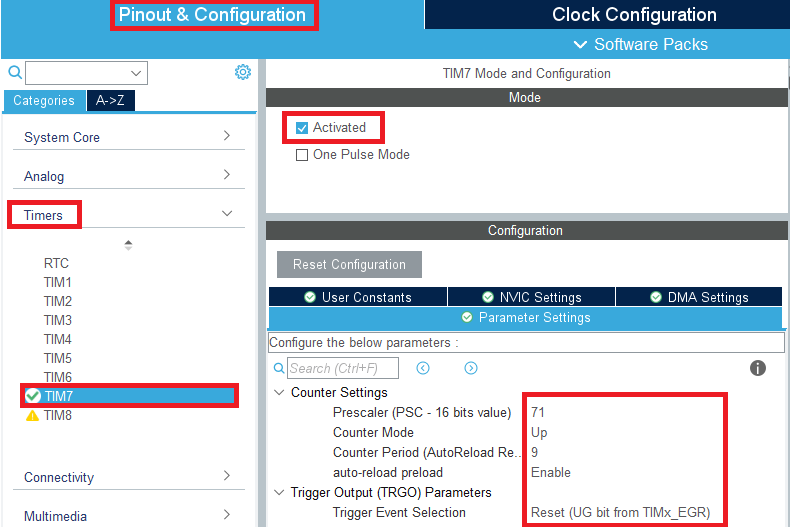
Timing formula
Timing time of this project: 10us
3. Engineering experience
Use the project files we provide to directly experience the corresponding functions of the development board.
Later tutorials do not provide this content to avoid duplication of content. You can go to [2. Development environment construction and use: engineering experience and transplantation] to view the operation
1. Open the project
Project file location
Project file path: Under the [Project Source Code] folder of the Chapter 4 tutorial

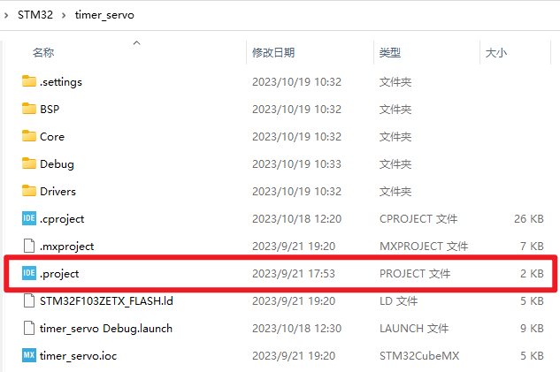
- Open project file
Copy the project file to the directory of English path, use STM32CubeIDE to open the project file, open the project file and select the .project file
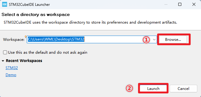
xxxxxxxxxxTip: You can create a new STM32 folder on the desktop and select the STM32 folder as the workspace when opening the project file.
4. Project configuration
This tutorial will completely demonstrate the configuration process. Later, the content of new project, chip selection, project settings, pin settings of SYS, RCC configuration, clock configuration and project configuration will be omitted. Any changes will be stated in the tutorial. .
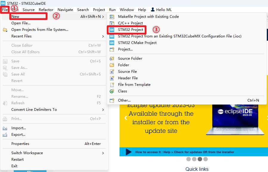
1. New project
Select workspace
The path of a new project or the path of an existing project file: the path cannot contain Chinese characters
- New Project
2、chip selection
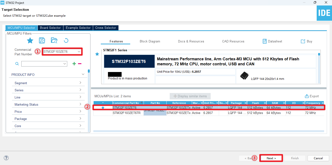
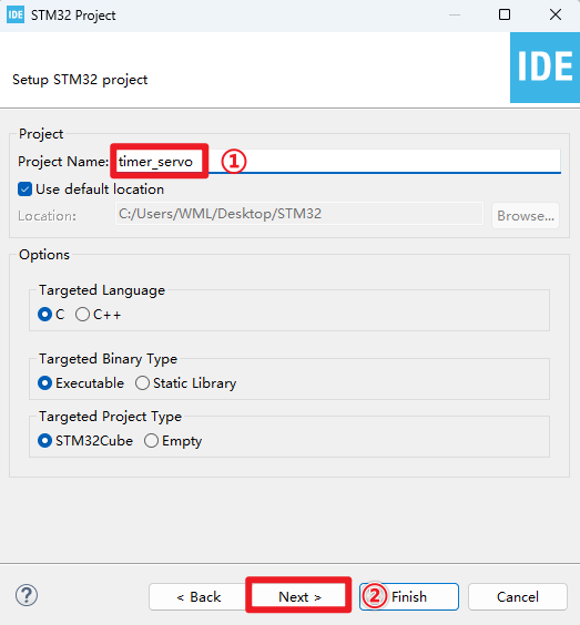
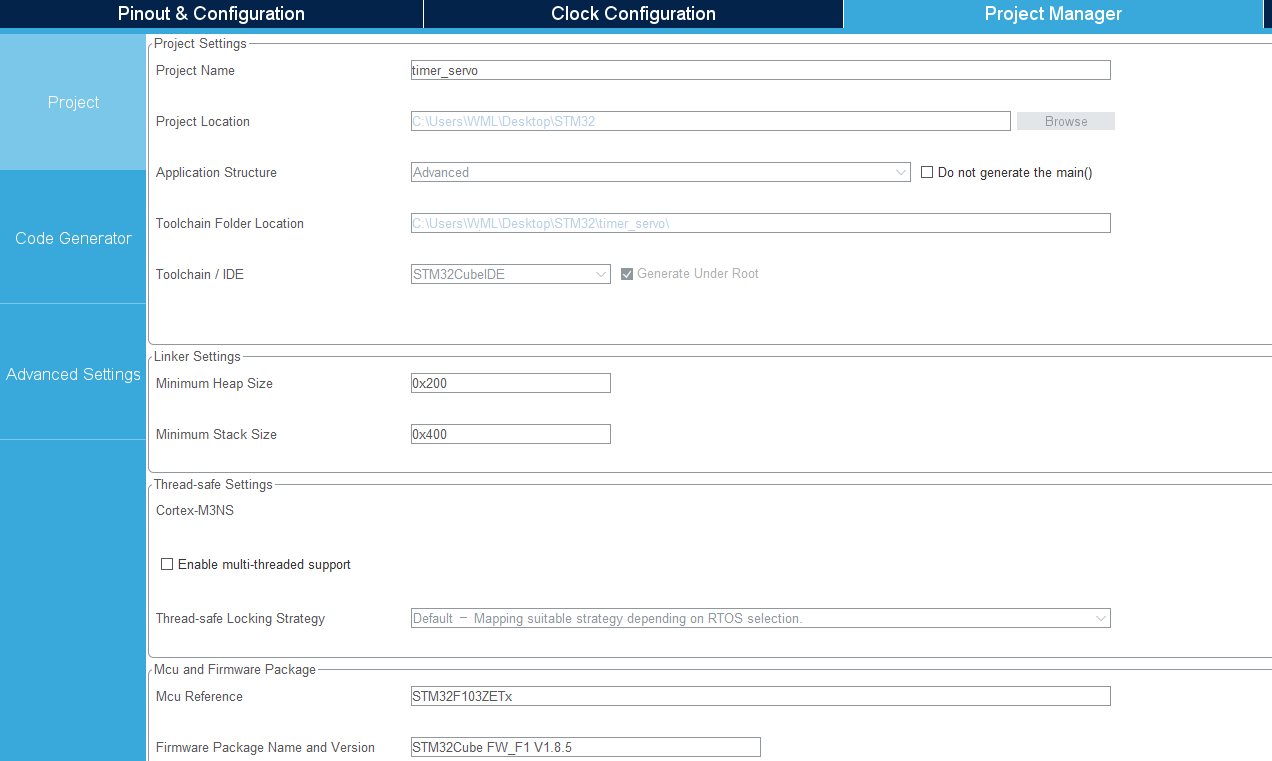
3、Project settings
- project name
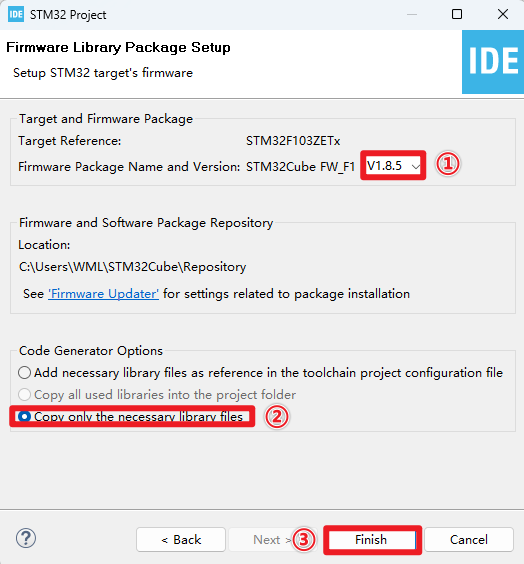
- Firmware version
4、Pin configuration
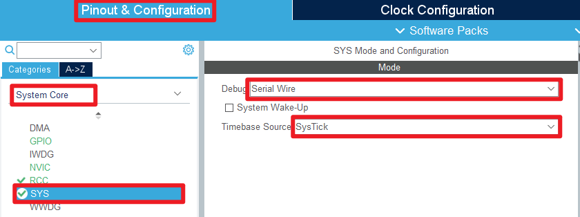
- SYS
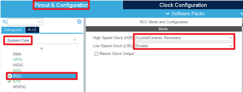
- RCC
- TIM
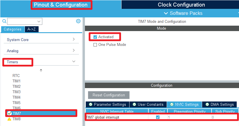
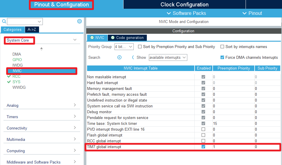
- NVIC
- GPIO
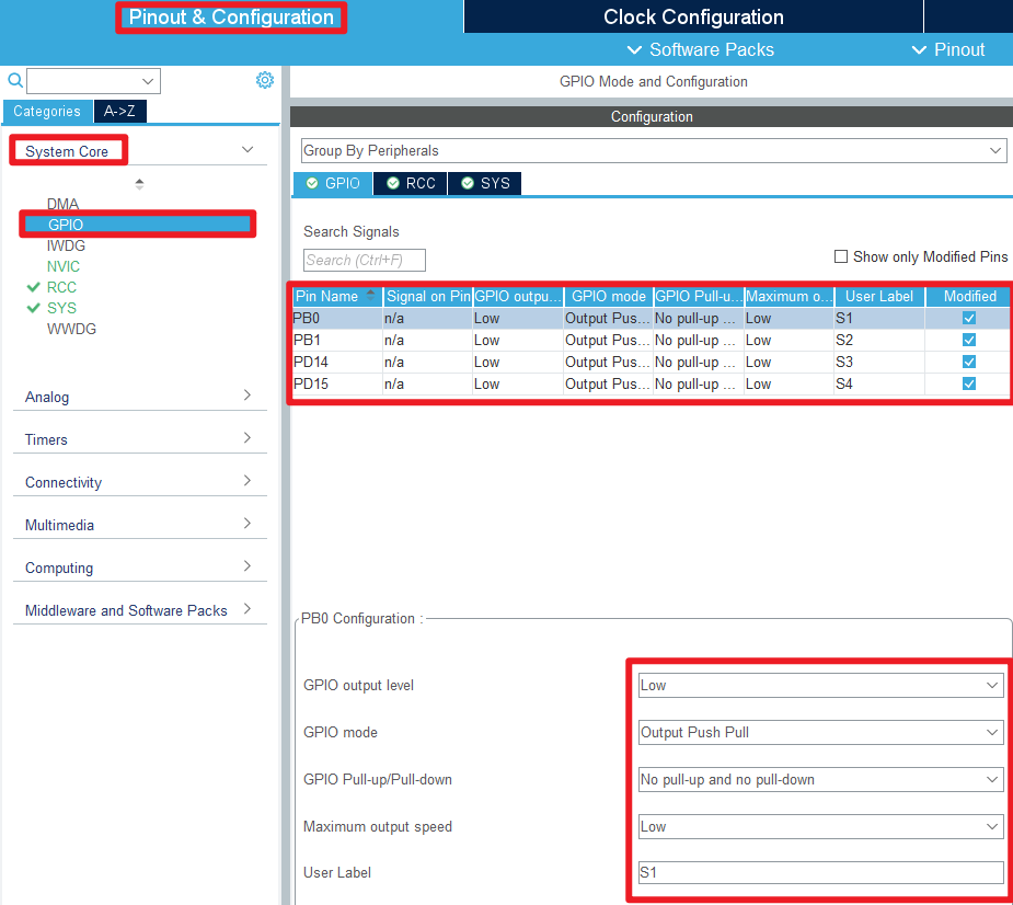
xxxxxxxxxxPlease refer to the figure above for specific configuration options. It is recommended to add tags. STM32CubeIDE will generate corresponding macro definitions.
5、Clock configuration
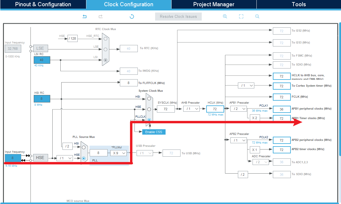
xxxxxxxxxxRefer to the options covered by the red arrows
6、Project configuration
Project
do not need to change
- Code Generator
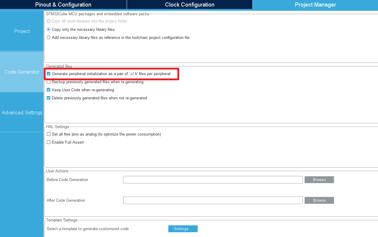
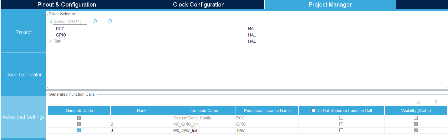
- Advanced Settings
7、Generate code
- Click on the "pinion" icon

xxxxxxxxxxClick here to save or the Ctrl+C shortcut key to generate code.
Edit code
User code must be located between USER CODE BEGIN and USER CODE END.
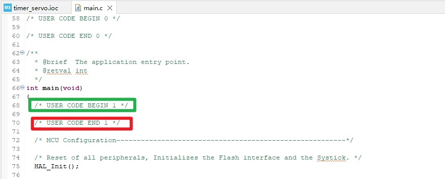
The above is the peripheral configuration and initialization code generation.
5. Main functions
It mainly introduces the functional code written by the user. For detailed code, you can open the project file provided by us yourself and enter the Bsp folder to view the source code.
1. User function
Function: PwmServo_Handle
| Function prototype | void PwmServo_Handle(void) |
|---|---|
| Function description | Called in timer interrupt, simulate output PWM signal |
| Input parameters | None |
| Output parameters | None |
| Notes | This function is called by the timer update interrupt callback function HAL_TIM_PeriodElapsedCallback |
Function: PwmServo_Angle_To_Pulse
| Function prototype | uint16_t PwmServo_Angle_To_Pulse(uint8_t angle) |
|---|---|
| Function description | Convert the specified angle into pulse width value |
| Input parameters | angle: rotation angle |
| Output parameters | Pulse width value |
Function: PwmServo_Init
| Function prototype | void PwmServo_Init(void) |
|---|---|
| Function description | Set the initial angle of each servo to 90° |
| Input parameters | None |
| Output parameters | None |
Function: PwmServo_Set_Angle
| Function prototype | void PwmServo_Set_Angle(uint8_t index, uint8_t angle) |
|---|---|
| Function description | Set the initial angle of a single servo |
| Input parameter 1 | index: servo serial number |
| Input parameter 2 | angle: rotation angle |
| Output parameters | None |
Function: PwmServo_Set_Angle_All
| Function prototype | void PwmServo_Set_Angle_All (uint8_t angle_s1, uint8_t angle_s2, uint8_t angle_s3, uint8_t angle_s4) |
|---|---|
| Function description | Set all servo rotation angles |
| Input parameter 1 | S1 servo rotation angle |
| Input parameter 2 | S2 servo rotation angle |
| Input parameter 3 | S3 servo rotation angle |
| Input parameter 4 | S4 servo rotation angle |
| Output parameters | None |
2. HAL library function analysis
Function: HAL_GPIO_Init
| Function prototype | void HAL_GPIO_Init(GPIO_TypeDef *GPIOx, GPIO_InitTypeDef *GPIO_Init) |
|---|---|
| Function description | Initialize GPIO pin parameters |
| Input parameter 1 | GPIOx: Set the GPIO port, x takes the value A, B, C, D, E, F, G |
| Input parameter 2 | GPIO_Init: GPIO initialization structure |
| Output parameters | None |
Function: HAL_GPIO_WritePin
| Function prototype | void HAL_GPIO_WritePin(GPIO_TypeDef *GPIOx, uint16_t GPIO_Pin, GPIO_PinState PinState) |
|---|---|
| Function Description | Set/Clear the specified pin |
| Input parameter 1 | GPIOx: Set the GPIO port, x takes the value A, B, C, D, E, F, G |
| Input parameter 2 | GPIO_Pin: Set the GPIO pin, x value is 0-15 |
| Input parameter 3 | PinState: Bit_RESET: clear the data port bit (low level); Bit_SET: set the data port bit (high level) |
| Output parameters | None |
Function: HAL_TIM_Base_Init
| Function prototype | HAL_StatusTypeDef HAL_TIM_Base_Init(TIM_HandleTypeDef *htim) |
|---|---|
| Function description | Initialize timer time base unit |
| Input parameters | htim: timer handle address |
| Output parameters | HAL status value: HAL_OK, HAL_ERROR, HAL_BUSY, HAL_TIMEOUT |
| Notes | This function will call the MCU underlying initialization function HAL_TIM_Base_MspInit to complete the settings of pins, clocks and interrupts |
Function: HAL_TIM_Base_MspInit
| Function prototype | void HAL_TIM_Base_MspInit(TIM_HandleTypeDef *htim); |
|---|---|
| Function description | Initialize the peripheral clock, GPIO and NVIC of the timer |
| Input parameters | htim: timer handle address |
| Output parameters | None |
Function: HAL_TIM_Base_MspDeInit
| Function prototype | void HAL_TIM_Base_MspDeInit(TIM_HandleTypeDef *htim) |
|---|---|
| Function description | Cancel the initialization of timer peripheral clock, GPIO and NVIC |
| Input parameters | htim: timer handle address |
| Output parameters | None |
HAL_TIM_IRQHandler: timer interrupt service function
| Function prototype | void HAL_TIM_IRQHandler(TIM_HandleTypeDef *htim) |
|---|---|
| Function description | Timer interrupt service function |
| Input parameters | htim: timer handle address |
| Output parameters | None |
| Notes | Internally, this function needs to first determine the interrupt type and clear the corresponding interrupt flag bit, and finally call the callback function |
HAL_TIM_PeriodElapsedCallback: Timer update interrupt callback function
| Function prototype | void HAL_TIM_PeriodElapsedCallback(TIM_HandleTypeDef *htim) |
|---|---|
| Function description | Timer update interrupt callback function |
| Input parameters | htim: timer handle address |
| Output parameters | None |
| Notes | This function is called by HAL_TIM_IRQHandler, and specific processing tasks can be written internally |
6. Program download
1. Serial port download
- Generate .hex file: Left-click the project → select "Properties"
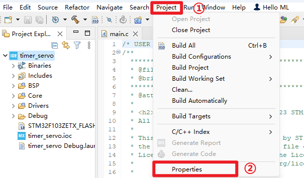
- Check the corresponding option
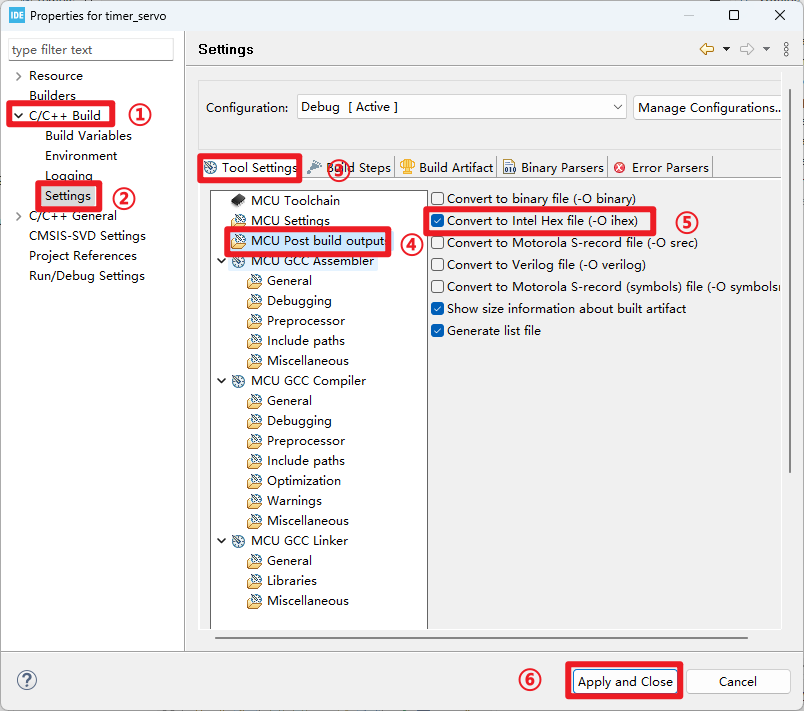
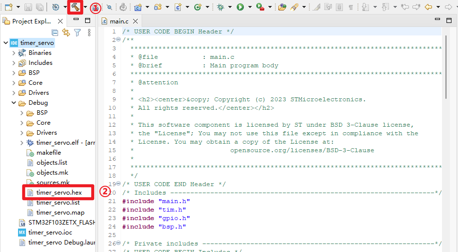
xxxxxxxxxxhex file location: under the Debug folder of the project file
Program Download
Use the Type-C data cable to connect the development board and the computer. For more detailed burning process, please refer to [2. Development environment construction and use: program download and simulation]
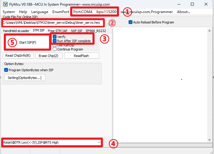
xxxxxxxxxxPay attention to the contents selected in the red box, which must be consistent
2、ST-Link Download
- Debug Settings: ST-Link → SWD
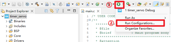
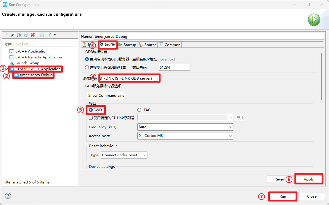
- Program Download: Click the Debug icon
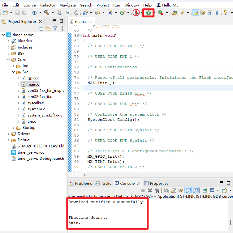
7. Experimental Phenomenon
After downloading the program successfully, press the RESET button of the development board and observe the development board phenomenon!
xxxxxxxxxxFor program download, please refer to [2. Development environment construction and use: program download and simulation]
Phenomenon:
S1 interface servo: cyclic rotation from 0° → 45° → 90° → 135° → 180° → 135° → 90° → 45° → 0°.
The provided project only controls the S1 interface servo. You can modify the interface function parameters by yourself to control other servos.For experimental phenomena, please see [Servo Control_Experimental Phenomenon.mp4]