2.4G handle control
2.4G handle control1. Opening Notes2. Experimental PreparationThe relationship between the 4 motor interfaces and the car is as follows:Hardware wiring:Overall wiringWiring pins3. Key code analysis4. Experimental phenomenon
1. Opening Notes
Please read the "Introduction to Motors and Usage" in the four-way motor driver board information first to understand the motor parameters, wiring methods, and power supply voltage you are currently using. To avoid burning the motherboard or motor.
Motor: The case and code take the 310 motor in our store as an example.
2. Experimental Preparation
National Race Chassis V2 Four-wheel Drive Version, 4*310 Motors, 7.4V Lithium Battery, PS2 Wireless Controller, STM32F103C8T6 Core Board.
The relationship between the 4 motor interfaces and the car is as follows:
M1 -> upper left motor (left front wheel of the car)
M2 -> lower left motor (left rear wheel of the car)
M3 -> upper right motor (right front wheel of the car)
M4 -> lower right motor (right rear wheel of the car)
Hardware wiring:
Overall wiring
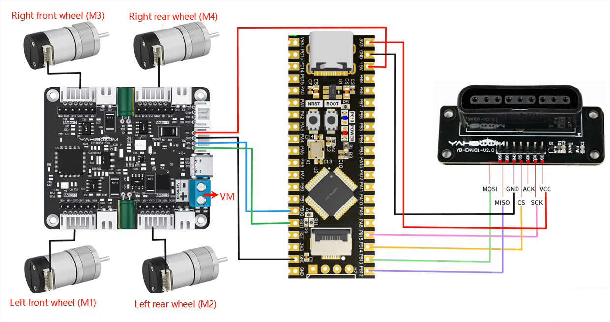
Wiring pins
| Four-way motor driver board | STM32C8T6 |
|---|---|
| 5V | 5V |
| GND | GND |
| SCL | PB10 |
| SDA | PB11 |
Take M1 motor as an example below, and other motors are similar.
| Motor | Four-way motor driver board (Motor) |
|---|---|
| M2 | M1- |
| VCC | 3V3 |
| A | H1A |
| B | H1B |
| GND | GND |
| M1 | M1+ |
| PS2 Wireless controller | STM32C8T6 |
|---|---|
| VCC | 3V3 |
| GND | GND |
| SCK | PB15 |
| CS | PB14 |
| MISO | PB12 |
| MOSI | PB13 |
| ACK | Not connected |
3. Key code analysis
- bsp_motor_iic.c
xxxxxxxxxx//控制带编码器类型的电机 Control the motor with encoder type//传入参数:4个电机的pwm PWM of 4 motors//此函数可以结合实时编码器的数据,来实现control_speed的功能 This function can combine the data of real-time encoder to realize the function of control_speedvoid control_pwm(int16_t m1,int16_t m2 ,int16_t m3,int16_t m4){ static uint8_t pwm[8]; pwm[0] = (m1>>8)&0xff; pwm[1] = (m1)&0xff; pwm[2] = (m2>>8)&0xff; pwm[3] = (m2)&0xff; pwm[4] = (m3>>8)&0xff; pwm[5] = (m3)&0xff; pwm[6] = (m4>>8)&0xff; pwm[7] = (m4)&0xff; i2cWrite(Motor_model_ADDR,PWM_Control_REG,8,pwm);}The control_pwm() function is used to control the four motors and send PWM signals to the motor driver board through i2c communication to adjust the speed and direction of the motor.
- pstwo.c
xxxxxxxxxx//判断是否为红灯模式 Judge whether it is red light mode//返回值;0,红灯模式 Return value: 0, red light mode//其他,其他模式 Others, other modesu8 PS2_RedLight(void){ CS_L; PS2_Cmd(Comd[0]); //开始命令 Start Command PS2_Cmd(Comd[1]); //请求数据 Request data CS_H; if( Data[1] == 0X73) return 0 ; else return 1;}...void Get_PS2data(void){ PS2_LX=PS2_AnologData(PSS_LX); PS2_LY=PS2_AnologData(PSS_LY); PS2_RX=PS2_AnologData(PSS_RX); PS2_RY=PS2_AnologData(PSS_RY); PS2_KEY=PS2_DataKey(); //DEBUG// printf("PS2_LX=%d ",PS2_LX);// printf("PS2_LY=%d ",PS2_LY);// printf("PS2_RX=%d ",PS2_RX);// printf("PS2_RY=%d ",PS2_RY);// printf("PS2_KEY=%d \r\n",PS2_KEY); }void PS2_CarControl(void){ //----摇杆直向控制---// //----Joystick vertical control---// if(PS2_LX == 128 && PS2_LY == 127) { control_pwm(0,0,0,0); } if(PS2_LY>=0&&PS2_LY<70)//直走 Go straight { control_pwm(1500,1500,1500,1500); } if(PS2_LY<=255 && PS2_LY>200 &&PS2_LX == 128)//后退 Back { control_pwm(-1500,-1500,-1500,-1500); } if(PS2_LX>=0&&PS2_LX<70)//左旋 Rotate Left { control_pwm(-1500,-1500,1500,1500); } if(PS2_LX<=255 && PS2_LX>200 && PS2_LY == 127)//右旋 Rotate Right { control_pwm(1500,1500,-1500,-1500); } //----摇杆斜向控制---// //----Joystick tilt control---// if(PS2_LX >= 0&&PS2_LX <= 90 && PS2_LY >= 0&&PS2_LY <= 70)//左前旋转 Left front rotation { control_pwm(0,0,1500,1500); } if(PS2_LX >= 165&&PS2_LX <= 255 && PS2_LY >= 0&&PS2_LY <= 70)//右前旋转 Right front rotation { control_pwm(1500,1500,0,0); } if(PS2_LX >= 0&&PS2_LX <= 90 && PS2_LY >= 165&&PS2_LY <= 255)//左后旋转 Left rear rotation { control_pwm(0,0,-1500,-1500); } if(PS2_LX >= 165&&PS2_LX <= 255 && PS2_LY >= 165&&PS2_LY <= 255)//右后旋转 Right rear rotation { control_pwm(-1500,-1500,0,0); } //---方向按键控制---// //---Direction button control---// switch(PS2_KEY){ case KEY_FORWARD: control_pwm(1500,1500,1500,1500); break; case KEY_BACK: control_pwm(-1500,-1500,-1500,-1500); break; case KEY_SPINRIGHT: control_pwm(1500,1500,-1500,-1500); break; case KEY_SPINLEFT: control_pwm(-1500,-1500,1500,1500); break; defalut: break; }}PS2_RedLight(): Checks whether the controller has entered simulation mode (traffic light mode).
Get_PS2data(): Reads the current status data of the PS2 joystick and buttons.
PS2_CarControl(): Determines the movement intention based on the joystick direction or button value, and calls control_pwm() to implement various actions of the car (forward, backward, rotation, tilt, etc.).
- main.c
xxxxxxxxxxint main(void){ uart_init(115200); //串口初始化为115200 Serial port initialized to 115200 PS2_Init(); //PS2端口初始化 PS2 port initialization IIC_Motor_Init(); delay_init(); while(1) { Get_PS2data(); if(!PS2_RedLight())//切换为模拟量输入模式时,开始控制小车 When switching to analog input mode, start controlling the car { PS2_CarControl(); } delay_ms(10); }}First, initialize the serial port, PS2 handle interface, i2c motor drive and delay function, then read the handle data continuously in the main loop. When the handle is detected in analog mode (traffic light mode), analyze the joystick data and control the motor movement through i2c communication. Finally, maintain a stable control cycle through 10ms delay to achieve real-time response to handle operation and precise motor control.
4. Experimental phenomenon
After connecting the car and burning the program to STM32, put the car on the ground and connect the car power supply. At this time, the receiver has a red light and a green light. It is waiting for pairing. Then turn on the handle switch. At this time, when the red and green lights on the receiver are always on, it means the match is successful. If the match is not successful, please check the wiring again. Press and hold the handle mode key to switch the mode. The mode in which the red and green lights on the top of the handle are always on is the analog value mode. At this time, you can press the direction key on the left side of the handle or push the left joystick; the up and down direction keys control the car to move forward and backward, and the left and right direction keys control the car to rotate left and right; the control effect of the left joystick is similar to that of the direction keys.