STM32-Automatic Driving
STM32-Automatic Driving1. Opening instructions2. Experimental preparationThe relationship between the 4 motor interfaces and the car is as follows:Hardware wiringOverall wiringWiring pins3. Key code analysis4. Experimental operation5. Experimental phenomenon
1. Opening instructions
Please read the "Introduction to Motors and Usage" in the four-way motor driver board information first to understand the motor parameters, wiring methods, and power supply voltage you are currently using. To avoid burning the motherboard or motor.
Motor: The case and code take the 310 motor of our store as an example.
2. Experimental preparation
National Race chassis V2 four-wheel drive version, 4*310 motors, 7.4V lithium battery, K210 vision module, STM32F103C8T6 core board.
The relationship between the 4 motor interfaces and the car is as follows:
M1 -> upper left motor (left front wheel of the car)
M2 -> lower left motor (left rear wheel of the car)
M3 -> upper right motor (right front wheel of the car)
M4 -> lower right motor (right rear wheel of the car)
Hardware wiring
Overall wiring
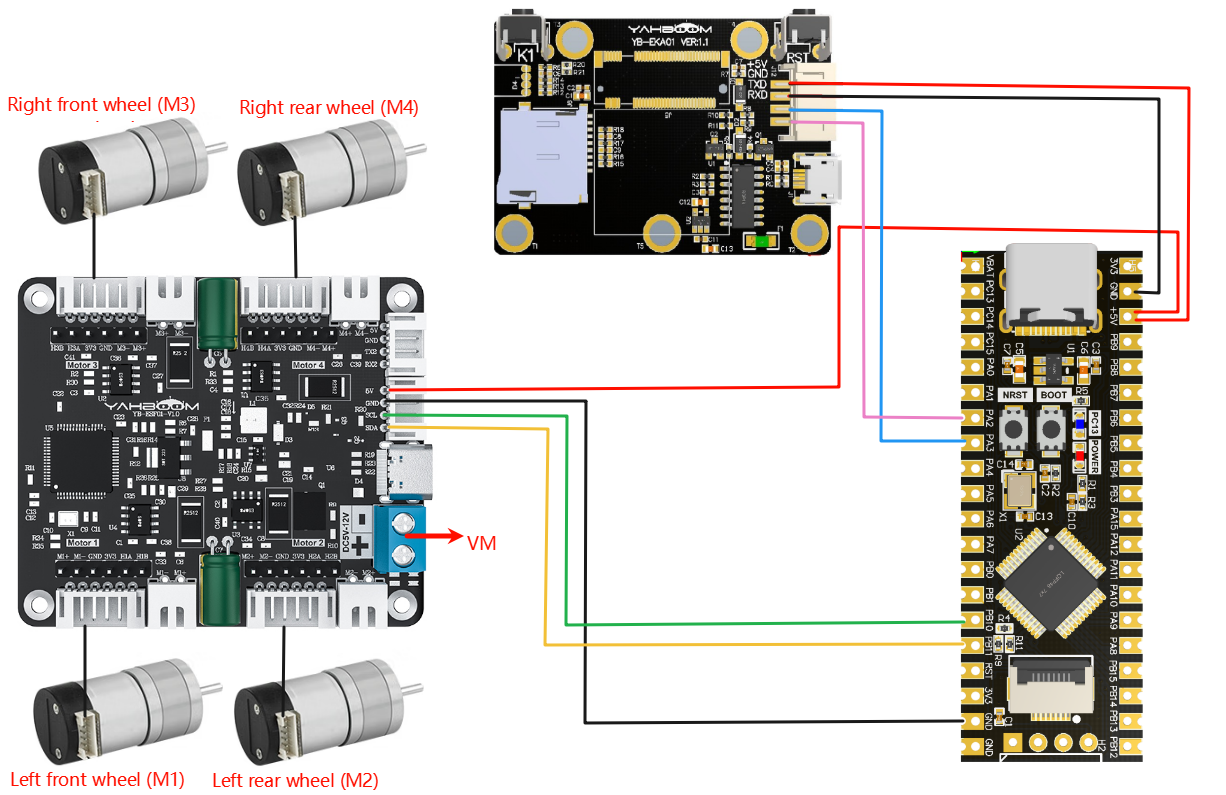
Wiring pins
| Four-way motor driver board | STM32C8T6 |
|---|---|
| 5V | 5V |
| GND | GND |
| SCL | PB10 |
| SDA | PB11 |
Take M1 motor as an example below, and other motors are similar.
| Motor | Four-way motor driver board (Motor) |
|---|---|
| M2 | M1- |
| VCC | 3V3 |
| A | H1A |
| B | H1B |
| GND | GND |
| M1 | M1+ |
| K210 | STM32C8T6 |
|---|---|
| 5V | 5V |
| GND | GND |
| TXD | PA3 |
| RXD | PA2 |
3. Key code analysis
- bsp.c
xvoid BSP_init(void){ SystemInit(); NVIC_PriorityGroupConfig(NVIC_PriorityGroup_2); delay_init();// delay_ms(1000); //等待红外稳定 Wait for infrared to stabilize USART1_init(115200); USART2_init(115200);//使用串口2 接收红外 Use serial port 2 to receive infrared RGB_Init(); IIC_Motor_Init();//四路电机通信初始化 Four-way motor communication initialization //放到最后才生效,不然还是无法正常使用 It will take effect at the end, otherwise it will not work properly. RCC_APB2PeriphClockCmd(RCC_APB2Periph_AFIO, ENABLE); GPIO_PinRemapConfig(GPIO_Remap_SWJ_JTAGDisable, ENABLE);//禁用jlink 只用SWD调试口,PA15、PB3、4做普通IO Disable jlink and use only SWD debug port, PA15, PB3, 4 as normal IO }The BSP_init() function is the key entry point for system initialization. First, the system clock is initialized through SystemInit(), and then the interrupt priority group is configured as group 2. Then the delay function, serial port (USART1 is used for debugging, USART2 is used to receive infrared signals), RGB light module, and IIC communication interface for four-way motor control are initialized in turn. Finally, the multiplexing function is enabled and JTAG is remapped to SWD, and the PA15, PB3, and PB4 pins are released for use as ordinary GPIOs to ensure that all peripherals work normally and are ready to run the main application.
- bsp_motor_iic.c
xxxxxxxxxx//只能控制带编码器类型的电机 Can only control motors with encoders//传入参数:4个电机的速度 Input parameters: speed of 4 motorsvoid control_speed(int16_t m1,int16_t m2 ,int16_t m3,int16_t m4){ static uint8_t speed[8]; speed[0] = (m1>>8)&0xff; speed[1] = (m1)&0xff; speed[2] = (m2>>8)&0xff; speed[3] = (m2)&0xff; speed[4] = (m3>>8)&0xff; speed[5] = (m3)&0xff; speed[6] = (m4>>8)&0xff; speed[7] = (m4)&0xff; i2cWrite(Motor_model_ADDR,SPEED_Control_REG,8,speed);}//控制带编码器类型的电机 Control the motor with encoder type//传入参数:4个电机的pwm PWM of 4 motors//此函数可以结合实时编码器的数据,来实现control_speed的功能 This function can combine the data of real-time encoder to realize the function of control_speedvoid control_pwm(int16_t m1,int16_t m2 ,int16_t m3,int16_t m4){ static uint8_t pwm[8]; pwm[0] = (m1>>8)&0xff; pwm[1] = (m1)&0xff; pwm[2] = (m2>>8)&0xff; pwm[3] = (m2)&0xff; pwm[4] = (m3>>8)&0xff; pwm[5] = (m3)&0xff; pwm[6] = (m4>>8)&0xff; pwm[7] = (m4)&0xff; i2cWrite(Motor_model_ADDR,PWM_Control_REG,8,pwm);}control_speed: Controls the speed of the motor. It splits the incoming four motor speed values into high and low bytes, and then sends them to the motor controller via the I2C protocol to set the motor speed.
control_pwm: Controls the PWM (pulse width modulation) value of the motor. It splits the incoming four motor PWM values into high and low bytes, and sends them to the motor controller via the I2C protocol to control the speed and direction of the motor.
- app_motor.c
xxxxxxxxxx// 返回当前小车轮子轴间距和的一半 Returns half of the current sum of the wheel axle distancesstatic float Motion_Get_APB(void){ return Car_APB;}...//直接控制速度 Directly control speedvoid Motion_Car_Control(int16_t V_x, int16_t V_y, int16_t V_z, uint8_t adjust){ float robot_APB = Motion_Get_APB(); speed_lr = 0; speed_fb = V_x; speed_spin = (V_z / 1000.0f) * robot_APB; if (V_x == 0 && V_y == 0 && V_z == 0) { control_speed(0,0,0,0); return; } speed_L1_setup = speed_fb - speed_spin; speed_L2_setup = speed_fb - speed_spin; speed_R1_setup = speed_fb + speed_spin; speed_R2_setup = speed_fb + speed_spin; if (speed_L1_setup > 1000) speed_L1_setup = 1000; if (speed_L1_setup < -1000) speed_L1_setup = -1000; if (speed_L2_setup > 1000) speed_L2_setup = 1000; if (speed_L2_setup < -1000) speed_L2_setup = -1000; if (speed_R1_setup > 1000) speed_R1_setup = 1000; if (speed_R1_setup < -1000) speed_R1_setup = -1000; if (speed_R2_setup > 1000) speed_R2_setup = 1000; if (speed_R2_setup < -1000) speed_R2_setup = -1000; //printf("%d\t,%d\t,%d\t,%d\r\n",speed_L1_setup,speed_L2_setup,speed_R1_setup,speed_R2_setup); control_speed(speed_L1_setup, speed_L2_setup, speed_R1_setup, speed_R2_setup); }The Motion_Car_Control function is used to calculate the speed values of the four motors based on the forward speed (V_x), lateral speed (V_y) and rotation speed (V_z) passed in, thereby controlling the movement of the car. The function obtains the wheel axle spacing of the car through Motion_Get_APB, and uses this value to calculate the rotation difference (speed_spin) between the left and right motors, thereby adjusting the rotational movement of the car. If the speed is zero, stop the motor directly; otherwise, control the speed of the four motors of the car according to the calculated speed value to ensure that the car moves in the predetermined direction and speed.
- revaction.c
xxxxxxxxxx// 获取命令标志 Get command flaguint8_t Get_CMD_Flag(void){ return New_CMD_flag;}...// 清除命令数据和相关标志 Clear command data and related flagsvoid Clear_CMD_Flag(void){ for (uint8_t i = 0; i < New_CMD_length; i++) { RxBuffer[i] = 0; } New_CMD_length = 0; New_CMD_flag = 0;}... //数据分析 data analysisvoid Upper_Data_Parse(uint8_t *data_buf, uint8_t num){ uint8_t func_id = *(data_buf + 3); switch (func_id) { /* 判断功能字:小车速度设置 Judgment function word: Trolley speed setting */ case FUNC_MOTION: { uint8_t parm = (uint8_t) *(data_buf + 4); int16_t Vx_recv = *(data_buf + 6) << 8 | *(data_buf + 5); int16_t Vy_recv = *(data_buf + 8) << 8 | *(data_buf + 7); int16_t Vz_recv = *(data_buf + 10) << 8 | *(data_buf + 9); uint8_t adjust = parm & 0x80; if (Vx_recv == 0 && Vy_recv == 0 && Vz_recv == 0) { control_pwm(0,0,0,0); } else { Motion_Car_Control(Vx_recv, Vy_recv, Vz_recv, (adjust==0?0:1)); } break; } /* 判断功能字:彩灯控制 Judgment function word: color light control */ case FUNC_RGB: { ... } default: break; }}The Get_CMD_Flag function returns the current command flag New_CMD_flag, which is used to check whether there is a new command; the Clear_CMD_Flag function clears the command flag and the data in the receiving buffer.
The Upper_Data_Parse function parses the data sent by the upper layer and performs different operations according to different function words (func_id). FUNC_MOTION parses and processes the speed setting command of the car, and calls Motion_Car_Control to control the movement or stop of the car.
- main.c
xxxxxxxxxx//1:520电机 2:310电机 3:测速码盘TT电机 4:TT直流减速电机 5:L型520电机 //1:520 motor 2:310 motor 3:speed code disc TT motor 4:TT DC reduction motor 5:L type 520 motorint main(void){ //硬件初始化 Hardware Initialization BSP_init(); ... Set_motor_type(2);//配置电机类型 Configure motor type delay_ms(100); Set_Pluse_Phase(20);//配置减速比 查电机手册得出 Configure the reduction ratio. Check the motor manual to find out delay_ms(100); Set_Pluse_line(13);//配置磁环线 查电机手册得出 Configure the magnetic ring wire. Check the motor manual to get the result. delay_ms(100); Set_Wheel_dis(48.00);//配置轮子直径,测量得出 Configure the wheel diameter and measure it delay_ms(100); Set_motor_deadzone(1300);//配置电机死区,实验得出 Configure the motor dead zone, and the experiment shows delay_ms(100); ... while(1) { if (Get_CMD_Flag()) { Upper_Data_Parse(Get_RxBuffer(), Get_CMD_Length()); Clear_CMD_Flag(); } }}MOTOR_TYPE: used to set the type of motor used. Modify the corresponding number according to the comments based on the motor you are currently using.
Call the BSP_init() function to initialize the hardware settings, and use Set_Motor(MOTOR_TYPE) to set the motor type and parameters. In the while(1) loop, Get_CMD_Flag detects whether there is a new command. If so, call Upper_Data_Parse to parse the data and control the car to run. After processing, use Clear_CMD_Flag to clear the command flag to ensure that the system continues to respond to the host computer instructions.
4. Experimental operation
- Burn the program to STM32.
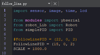
- Download the car drive library and PID control library in the K210\library directory to the root directory of the memory card in advance.
- Open CanMV IDE and download the follow_line.py code into the K210 module.
- Connect all the wires of the car.
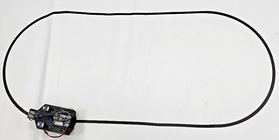
- Put the car into the map of visual patrol, move the K210 module bracket to the appropriate angle, and connect the power supply.
- After the system is initialized, the LCD displays the camera image, and there is a white box in the middle of the screen. Please move the car to fill the white box with the color to be identified, and wait for the white box to turn green to start collecting colors. After the collection is completed, the green box disappears and the program starts running.
5. Experimental phenomenon
After connecting the power supply, wait for the system to be initialized, the LCD displays the camera image, and there is a white box in the middle of the screen. Please put the color to be identified in the white box, and wait for the white box to turn green to start collecting colors. After the collection is completed, the green box disappears and the program starts running.
The car will move forward along the color just identified in the green box.
If you find that the car often fails to patrol the line, please check whether the car can recognize the corresponding color at each position. If the car reacts too slowly or too quickly, you can adjust the value of FollowLinePID appropriately.