CCD dual tracking-Mini chassis
CCD dual tracking-Mini chassis1.Experimental Purpose2.Experimental preparation3.Experimental wiring3.1 Jumpers are required for the wiring of the ROS expansion board and the 310 motor3.2 3.2 Wiring of ROS expansion board, linear CCD module, and OLED screen4.Program source code analysis5.note6.experimental result
1.Experimental Purpose
Through the previous experiment, we learned how the linear CCD module tracks along the black line. In this experiment, we increased our efforts to have the CCD track between the two black lines.
2.Experimental preparation
This experiment requires an ROS expansion board, a Chinese racing chassis car, a 310 motor, a 7.4V battery, a linear CCD module, and an OLED screen (not required)
These hardware can be purchased from Yabo Intelligent's Taobao store
3.Experimental wiring
3.1 Jumpers are required for the wiring of the ROS expansion board and the 310 motor
The line sequence of the two is shown in the following figure:
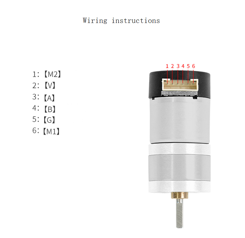
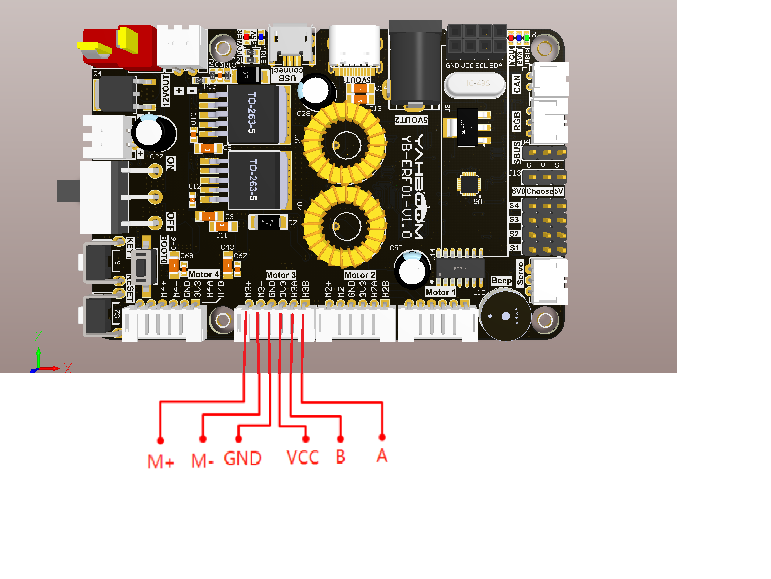 M1--->M+
M2--->M-
M1--->M+
M2--->M-
3.2 3.2 Wiring of ROS expansion board, linear CCD module, and OLED screen
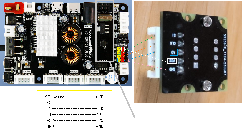
4.Program source code analysis
This project introduces a real-time operating system for Freeros, and we will look at vTask ourselves_ The CCD thread function is sufficient, and other thread functions are not closely related to this experiment. Interested parties can analyze it on their own. vTask_CCD:This task is to first determine whether the freeros system is normal, and if it is normal, enter the APP_ CCD_ The following will focus on analyzing the processing function for the tracking task of Handle
void APP_CCD_Handle(void){ CCD_Read_TSL(); g_ccd_median = 64 - CCD_Find_Median(); if((g_ccd_median>-5&&g_ccd_median<5)||g_ccd_median == 64)//Straight travel { g_ccd_median = 0; } OLED_Show_CCD_Image(CCD_Get_ADC_128X32()); pid_output = (int)(APP_CCD_PID_Calc(g_ccd_median)); Motion_Ctrl(CCD_SPEED, 0, pid_output, 0);}- CCD_Read_TSL:This function is used to drive a linear CCD camera for data collection.
- CCD_Find_Median:The dynamic threshold algorithm used inside extracts the position of the current camera on the black and white lines.
- OLED_Show_CCD_Image:The purpose of this function is to display the waveform data collected by CCD.
- APP_CCD_PID_Calc:The PID algorithm is used inside, and the processed data is controlled for the speed of four motors based on the dynamic threshold algorithm.
- Motion_Ctrl:According to the PWM output of the PID algorithm, a motor is driven to perform a tracking of the car.
5.note
- Because this car is a differential car, the speed should not be too fast, as it may cause undetectable black lines and make it difficult to turn
- The experiment in this tutorial adopts the slowest speed, and those who need to adjust it faster need to adjust the PID parameters themselves.
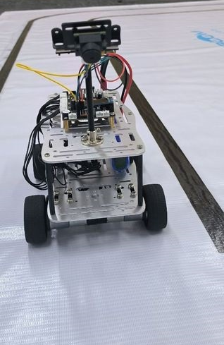
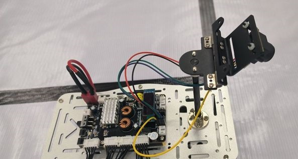
- The installation position and height of the CCD camera in this tutorial are shown in the following figure: (Different positions and heights may also affect the adjustment of pid parameters)
- The experimental source code of this tutorial is only applicable to the experimental car, and is for reference only for other car source codes.
6.experimental result
You can see that the car is tracking normally on the black and white line. For a detailed tracking video, please refer to the introduction video of the CCD module on Taobao, a flagship store of Yabo Intelligent.
Alternatively, check out a short follow-up video of this experiment.
Other reference tutorials: https://blog.csdn.net/Gxust_Veneno/article/details/119797411