Collision limit detection module: external interrupt control LED
Hardware wiring
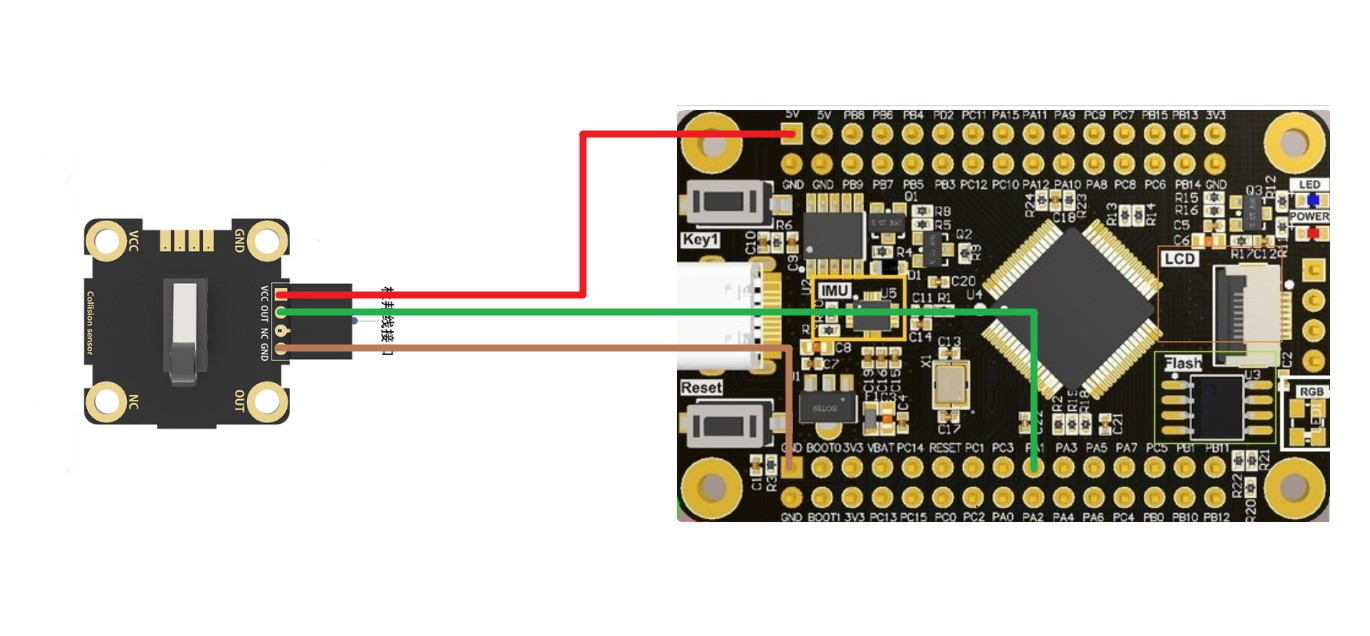
| Collision limit detection module | STM32F103RCT6 |
|---|---|
| VCC | 5V/3.3V |
| OUT | PA1 |
| NC | |
| GND | GND |
Brief principle
Circuit schematic
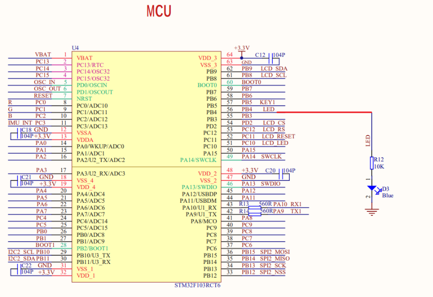
The LED is connected to the PB4 pin, you need to pay attention to the pin configuration of PB4 (see the code for the specific configuration):
PB4 output high level, LED on;
The PB4 output is low and the LED is off.
When a collision occurs in the collision detection module, OUT outputs a high level When PA1 generates a rising edge signal, the program enters an external interrupt and the LED is lit.
Main code
main.c
x#include "stm32f10x.h"#include "LED.h"#include "EXTI.h"int main(void){LED_Init();//LED初始化(PB4)EXTI1_Init();//外部中断1初始化(PA1 EXTI1)while(1){}}
LED.c
xxxxxxxxxx#include "LED.h"void LED_Init(void)//LED初始化(PB4){GPIO_InitTypeDef GPIO_InitStructure;/* Enable GPIOB and AFIO clocks *//* 使能GPIOB和功能复用IO时钟 */RCC_APB2PeriphClockCmd(RCC_APB2Periph_GPIOB | RCC_APB2Periph_AFIO, ENABLE);/* JTAG-DP Disabled and SW-DP Enabled *//* 禁用JTAG 启用SWD */GPIO_PinRemapConfig(GPIO_Remap_SWJ_JTAGDisable, ENABLE);/* Configure PB4 in output pushpull mode *//* 配置PB4 推挽输出模式 */GPIO_InitStructure.GPIO_Pin = GPIO_Pin_4;GPIO_InitStructure.GPIO_Mode = GPIO_Mode_Out_PP;GPIO_InitStructure.GPIO_Speed = GPIO_Speed_50MHz;GPIO_Init(GPIOB, &GPIO_InitStructure);/* Set the GPIOB port pin 4 *//* 设置PB4端口数据位 */GPIO_WriteBit(GPIOB, GPIO_Pin_4, Bit_RESET);}
LED.h
xxxxxxxxxx#ifndef __LED_H__#define __LED_H__#include "stm32f10x.h"void LED_Init(void);//LED初始化(PB4)#endif
EXTI.c
xxxxxxxxxx#include "EXTI.h"void EXTI1_Init(void)//外部中断1初始化(PA1 EXTI1){EXTI_InitTypeDef EXTI_InitStructure;GPIO_InitTypeDef GPIO_InitStructure;NVIC_InitTypeDef NVIC_InitStructure;/* Enable GPIOA and AFIO clock *//* 使能GPIOA AFIO时钟 */RCC_APB2PeriphClockCmd(RCC_APB2Periph_GPIOA | RCC_APB2Periph_AFIO, ENABLE);/* Configure PA1 pin as input floating *//* 配置PA1上拉输入模式 */GPIO_InitStructure.GPIO_Pin = GPIO_Pin_1;GPIO_InitStructure.GPIO_Mode = GPIO_Mode_IPU;GPIO_Init(GPIOA, &GPIO_InitStructure);/* Connect EXTI1 Line to PA1 pin *//* 连接EXTI1到PA1引脚 */GPIO_EXTILineConfig(GPIO_PortSourceGPIOA, GPIO_PinSource1);/* Configure EXTI1 line *//* 配置EXTI1 */EXTI_InitStructure.EXTI_Line = EXTI_Line1;EXTI_InitStructure.EXTI_Mode = EXTI_Mode_Interrupt;EXTI_InitStructure.EXTI_Trigger = EXTI_Trigger_Rising;//上升沿触发EXTI_InitStructure.EXTI_LineCmd = ENABLE;EXTI_Init(&EXTI_InitStructure);/* Enable and set EXTI1 Interrupt to the lowest priority *//* 使能和配置EXTI1优先级及中断向量入口地址 */NVIC_InitStructure.NVIC_IRQChannel = EXTI1_IRQn;NVIC_InitStructure.NVIC_IRQChannelPreemptionPriority = 0x00;NVIC_InitStructure.NVIC_IRQChannelSubPriority = 0x00;NVIC_InitStructure.NVIC_IRQChannelCmd = ENABLE;NVIC_Init(&NVIC_InitStructure);}void EXTI1_IRQHandler(void){if(EXTI_GetITStatus(EXTI_Line1) != RESET){/* 给PB4高电平,控制LED亮 */GPIO_WriteBit(GPIOB, GPIO_Pin_4, Bit_SET);/* Clear the EXTI line 1 pending bit *//* 清除EXTI1中断标志位 */EXTI_ClearITPendingBit(EXTI_Line1);}}
EXTI.h
xxxxxxxxxx#ifndef __EXTI_H__#define __EXTI_H__#include "stm32f10x.h"void EXTI1_Init(void);//外部中断1初始化(PA1 EXTI1)#endif
Phenomenon
After downloading the program, press the Reset key once, and the downloaded program will run.
When the collision detection module detects a collision, the LED is lit. If you need to restore the detection mode again, you need to press the Reset button on the board or power off once, and the LED will turn off.