5. Control PWM servo
5. Control PWM servo5.1. Experimental Objectives5.2. Experiment Preparation5.3. Experimental Effect5.4 Program Source Code
5.1. Experimental Objectives
To control the rotation of a PWM servo on a robot.
5.2. Experiment Preparation
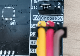
The position in the red box in the following picture is the interface of the PWM servo, including a servo voltage switching interface and four servo interfaces. The servo voltage switching interface can be inserted into the jumper cap to select 5V or 6.8V voltage, if not inserted into the jumper cap, it will not be able to control the PWM servo. The black interface of the servo interface is GND, the red interface is 5V power positive, and the yellow interface is signal.
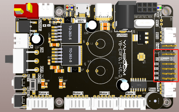
The servo connector must be plugged in corresponding to the color and must not be plugged in backwards.
Rosmaster_Lib library functions needed for PWM servo heads:
xxxxxxxxxxset_pwm_servo(servo_id, angle)Parameter explanation: servo control, servo_id: corresponding ID number: S1 = 1, S2 = 2, S3 = 3, S4 = 4, angle: corresponding servo angle value
servo_id=[1, 4], angle=[0, 180]
Return value: none.
xxxxxxxxxxset_pwm_servo_all(angle_s1, angle_s2, angle_s3, angle_s4)Parameter explanation: control the angle of four PWMs at the same time, angle_sX=[0, 180]
Return value: None.
5.3. Experimental Effect
Refer to 4.3.1, 4.3.2 to check the ROS expansion board as well as into the Docker container, and then run the program, in the jupyter lab interface, double-click to enter the /root/yahboomcar_ros2_ws/Rosmaster/Sample, double-click to select the 5.pwm_servo.ipynb, and then step-by-step click on the 4.3. 3 The button shown in the figure operates the program.
5.4 Program Source Code
Enter the docker, refer to the code path: /root/yahboomcar_ros2_ws/Rosmaster/Sample/5.pwm_servo.ipynb.