Buzzer control
Buzzer controlDevice connectionHardware connectionSoftware connectionBuzzer controlControl PrincipleControl PinCode AnalysisExperimental results
Control the passive buzzer on the Robduino expansion board to sound.
Device connection
Hardware connection
Use Type-B data cable to connect Arduino Uno and computer.
Software connection
Open the "Arduino IDE" software and select the model and serial port number corresponding to the development board.
Buzzer control
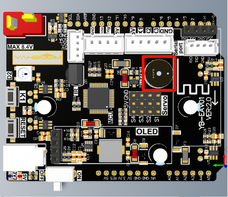
The location selected by the red box is the location of the buzzer module:
Control Principle
Buzzers are divided into two types: active buzzers and passive buzzers. Active buzzers: require external working voltage to emit fixed frequency sound; Passive buzzers: require external circuit to provide driving signal, and control the pitch and loudness of the sound by changing the frequency and amplitude of the signal.
Arduino's tone library can be used to control the digital pin on the Arduino board to output a square wave signal of a specified frequency, thereby driving the buzzer connected to the pin to play the specified tone.
Control Pin
| Peripheral Module | Arduino Uno |
|---|---|
| Buzzer | 10 |
Code Analysis
Here is only a brief introduction to the code content. For detailed code, it is recommended to refer to the corresponding code file, which is provided in the download area!
Define BUZZER control pins
x// 定义蜂鸣器控制引脚 Define BUZZER control pins#define BUZZER_PIN 10
Initialization Code
xvoid setup() {pinMode(BUZZER_PIN, OUTPUT); // 设置蜂鸣器引脚输出模式 Set the buzzer pin output mode}
Looping code
xxxxxxxxxxvoid loop() {tone(BUZZER_PIN, 1000); // 播放频率为1000HZ的音调 Play a 1000 Hz tonedelay(100);noTone(BUZZER_PIN); // 停止发声 Stop playdelay(5000);}
Experimental results
After compiling the program successfully, upload the code to the Arduino Uno development board.
After the program is started, the buzzer will beep every 5 seconds!
xxxxxxxxxxThe burning program cannot use other programs to occupy the serial port or external serial communication module (for example: WiFi camera module), otherwise the program cannot be burned or an error message will be prompted!