Movelt kinematic design
1. Pose description in 3D space
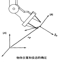
First, a coordinate system is defined. Relative to this coordinate system, the position of a point can be represented by a 3D column vector; the orientation of a rigid body can be represented by a 3×3 rotation matrix. The 4×4 homogeneous transformation matrix can unify the description of the position and posture (position) of a rigid body. It has the following advantages:
(1) It can describe the position and posture of a rigid body and the relative position and posture (description) of a coordinate system.
(2) It can represent the transformation of a point from the description of one coordinate system to the description of another coordinate system (mapping).
(3) It can represent the transformation (operator) of the posture description before and after the rigid body moves.
- Position Description - Position Vector
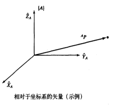
Use three mutually orthogonal unit vectors with arrows to represent a coordinate system {A}.
Then, the spatial position of point p in the coordinate system {A} is expressed as:
- Description of orientation - rotation matrix
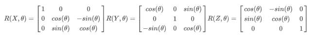
The commonly used rotation transformation matrix is to rotate an angle around the X axis, around the Y axis or around the Z axis.
They as shown below.
- Non-homogeneous representation
After a rotation R and a translation t, vector a is obtained as $a': a'=R*a+t$
- Homogeneous representation
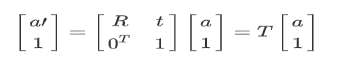
The general rotation matrix R is:
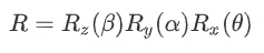
The rotation matrix here rotates by an angle of θ around the X axis, then by an angle of α around the Y axis, and finally by an angle of β around the Z axis.
- Right-hand rule
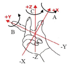
The thumb points to X, the index finger points to Y, and the middle finger points to Z.
- RPY and Euler Angles
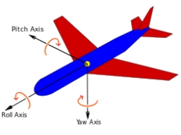
The rotation order according to the local coordinate system is Z-->Y-->X, which is called eulerYPR (Yaw Pitch Roll);
The rotation order according to the external coordinate system (reference coordinate system) is x-->y-->z, which is called RPY (Roll Pitch Yaw);
When describing the same posture, the above two representations are equivalent, that is, the angle values of Yaw Pitch Roll are the same.
Definition: Yaw ϒ; Pitch β; Roll α
- Quaternion method
The general definition is that the vector is represented by a scalar and three imaginary axes, which is called a quaternion. The range of each data [x, y, z, w] is [-1,1].
2. Start the robot simulation
2.1 Start roscore
- If you are using Jetson Orin NX/Jetson Orin Nano board. You need to enter the Docker environment using the following command.
sh ~/start_docker.shroscore
- If you are using Jetson Nano board. You need to enter the following command directly.
xxxxxxxxxxroscore
2.2 Start simulation
Open a new terminal.
- If you are using Jetson Orin NX/Jetson Orin Nano board. You need to enter the Docker environment using the following command.
xxxxxxxxxxsh ~/start_docker.sh
- If you are using Jetson Nano board. You need to enter the following command directly.
xxxxxxxxxxroslaunch jetcobot_moveit jetcobot_moveit.launch
3. Drive real robotic arm
Open a new terminal.
- If you are using Jetson Orin NX/Jetson Orin Nano board. You need to enter the Docker environment using the following command.
xxxxxxxxxxsh ~/start_docker.sh
- If you are using Jetson Nano board. You need to enter the following command directly.
xxxxxxxxxxrosrun jetcobot_moveit sync_plan.py
Note: After the program driving the real machine is running, the robotic arm will follow the movement of the simulated robot.
Please be careful not to place other objects around to avoid being hit by the robotic arm.
4. Start program
Open a new terminal.
- If you are using Jetson Orin NX/Jetson Orin Nano board. You need to enter the Docker environment using the following command.
xxxxxxxxxxsh ~/start_docker.sh
- If you are using Jetson Nano board. You need to enter the following command directly.
xxxxxxxxxxrosrun jetcobot_moveit 02_set_pose_plan.py
Code path:~/jetcobot_ws/src/jetcobot_moveit/scripts/02_set_pose_plan.py
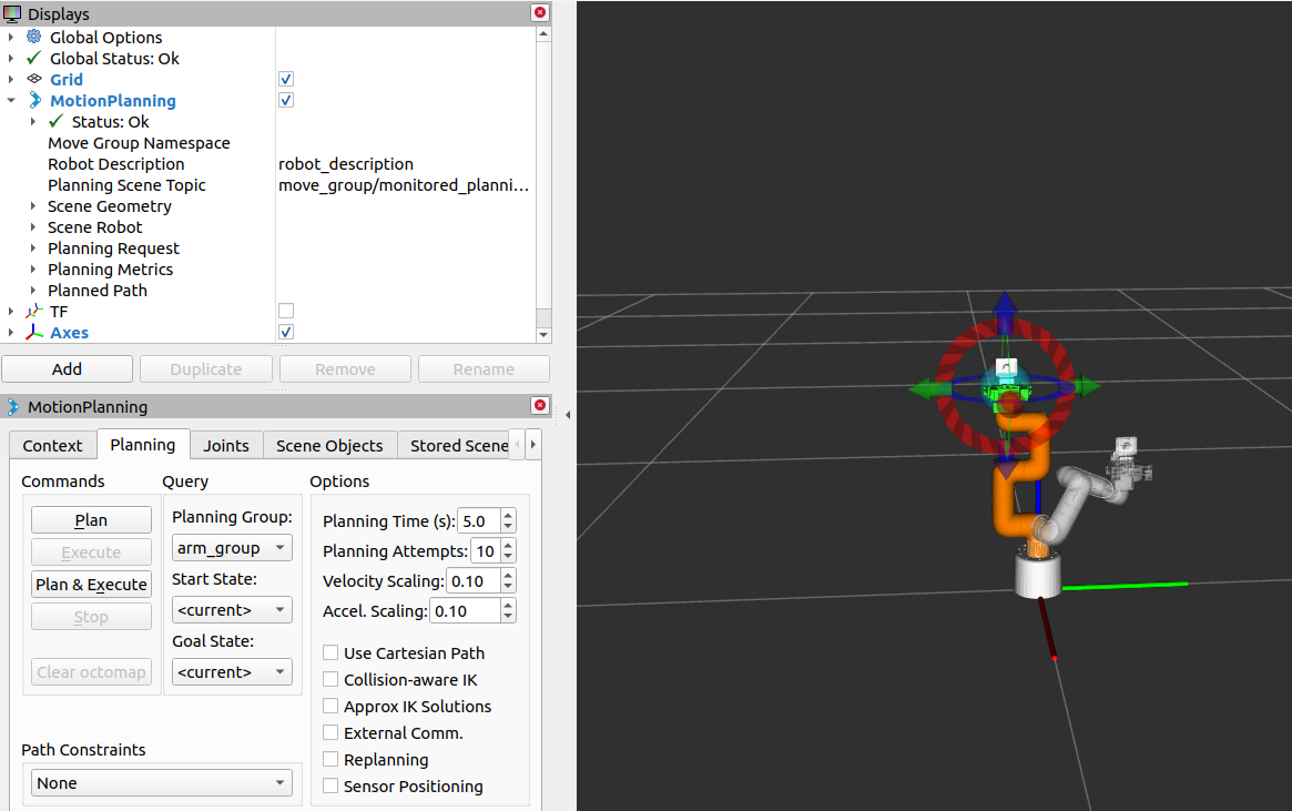
Experimental phenomenon: We can see that the robotic arm will move to the position we set.
As shown in the figure, the robotic arm plans a posture, and the robot arm will move along with it.
Close the process: Press [ctrl+c].
If it fails to close, press [ctrl+z].