01. Interface distribution of expansion board
01. Interface distribution of expansion board1.1. Component distribution diagram of the front of the expansion board1.2. Component distribution diagram on the back of the expansion board
1.1. Component distribution diagram of the front of the expansion board
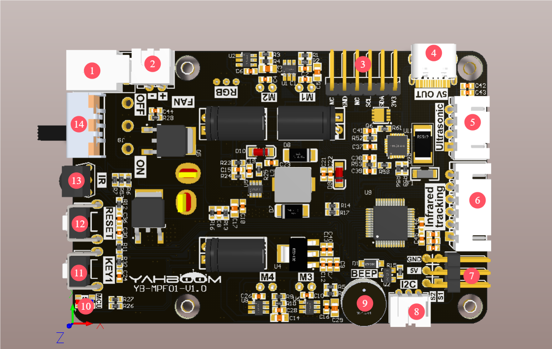
①Charging port: connect to the matching 8.4V charger
②Cooling fan interface: connect to the cooling fan
③OLED screen interface: connect to the OLED screen
④Type-C interface: provide DC 5V to the outside, support the Raspberry Pi 5 power supply protocol, provide 5.1V/5A power supply for the Raspberry Pi 5, only power supply can not communicate.
⑤Ultrasonic interface: connect to the ultrasonic sensor module
⑥Four-way patrol module interface: connect to the four-way patrol module
⑦PWM servo interface: connect to two PWM servos
⑧I2C interface: used to communicate with the Raspberry Pi 5 motherboard
⑨Buzzer: active buzzer
⑩Power indicator and MCU indicator: indicate the current status of the product.
⑪Key KEY1: user function key, which can realize custom functions through programming.
⑫ Button RESET: Onboard MCU reset button
⑬ Infrared receiver: used to receive infrared signals, used with the matching infrared remote control
⑭ Power switch: main power switch
1.2. Component distribution diagram on the back of the expansion board
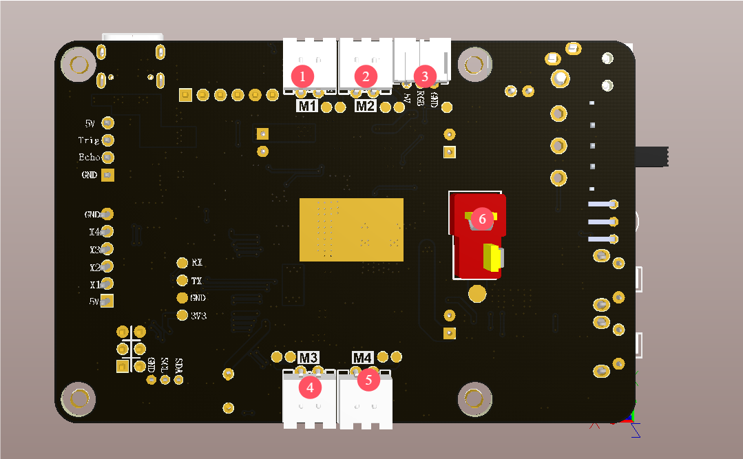
① Motor M1 interface: connected to the upper left corner TT DC motor
② Motor M2 interface: connected to the lower left corner TT DC motor
③ RGB colorful light bar interface: connected to the RGB colorful light bar.
④ Motor M3 interface: connected to the upper right corner TT DC motor
⑤ Motor M4 interface: connected to the lower right corner TT DC motor
⑥ T-type DC 6.5V~8.4V power input interface: as the main power input of the expansion board, connected to a DC 6.5V~8.4V power supply or a 6.5V~8.4V battery.