Bluetooth module-Data reading (USART)
Bluetooth module-Data reading (USART)Hardware connectionControl principleMaster-slave modeHost modeSlave modeSoftware configurationPin definitionSoftware codeControl functionExperimental phenomenon
The tutorial combines the Bluetooth module to demonstrate multi-serial communication.
Serial port 5 receives the data sent by the Bluetooth module and outputs it through serial port 1The tutorial only introduces the standard library project code
Hardware connection
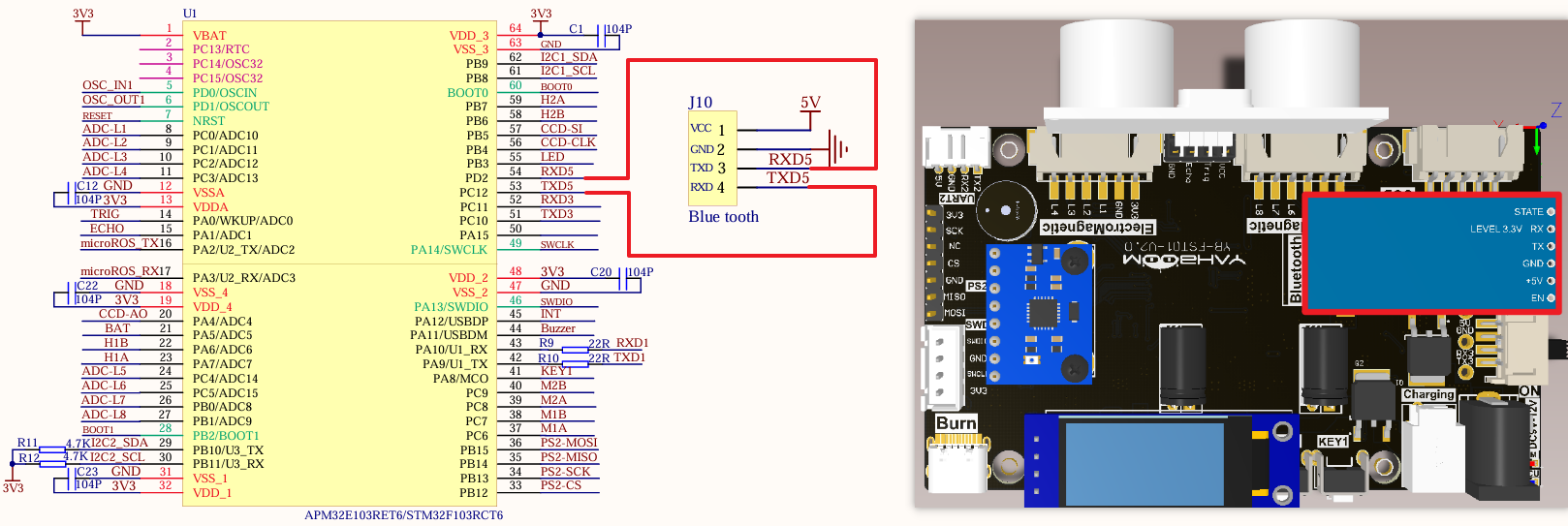
Install the Bluetooth module to the corresponding interface:
| Bluetooth module | Development board |
|---|---|
| VCC | VCC |
| TXD | RXD5 |
| RXD | TXD5 |
| GND | GND |
Control principle
The mobile phone is paired with the Bluetooth module (slave) on the balance car through the built-in Bluetooth (host). The Bluetooth module receives the data of the balance car APP and sends it to the development board for analysis.
xxxxxxxxxxThe Bluetooth module sends the data transmitted by the mobile phone APP to the development board through TXD. The development board then parses the received data and obtains the corresponding command data. Later, the movement state of the car can be controlled according to this command data.
Master-slave mode
The host is responsible for managing the communication process and controlling data transmission, while the slave performs corresponding operations according to the host's instructions.
Host mode
The controller in Bluetooth communication is responsible for initiating connection requests and controlling the entire communication process.
Slave mode
Passively wait for the host's connection request and accept the host's control.
Software configuration
Pin definition
| Main control chip | Pin | Main function (after reset) | Default multiplexing function | Redefine function |
|---|---|---|---|---|
| STM32F103RCT6 | PD2 | PD2 | TIM3_ETR/USART5_RX/SDIO_CMD | |
| STM32F103RCT6 | PC12 | PC12 | USART5_TX/SDIO_CK | USART3_CK |
Software code
Since the default function of the pin is the ordinary IO pin function, we need to use the default multiplexing function.
xxxxxxxxxxProduct supporting data source code path: Attachment → Source code summary → 2.Extended_Course → 6.Bluetooth
Control function
The tutorial only briefly introduces the code, and you can open the project source code to read it in detail.
uart_init
xvoid uart_init(u32 bound){//GPIO port settingsGPIO_InitTypeDef GPIO_InitStructure;USART_InitTypeDef USART_InitStructure;NVIC_InitTypeDef NVIC_InitStructure;RCC_APB2PeriphClockCmd(RCC_APB2Periph_USART1|RCC_APB2Periph_GPIOA, ENABLE); //Enable USART1, GPIOA clock//USART1_TX GPIOA.9GPIO_InitStructure.GPIO_Pin = GPIO_Pin_9; //PA.9GPIO_InitStructure.GPIO_Speed ••= GPIO_Speed_50MHz;GPIO_InitStructure.GPIO_Mode = GPIO_Mode_AF_PP; //Multiplex push-pull outputGPIO_Init(GPIOA, &GPIO_InitStructure);//Initialize GPIOA.9//USART1_RX GPIOA.10 initializationGPIO_InitStructure.GPIO_Pin = GPIO_Pin_10;//PA10GPIO_InitStructure.GPIO_Mode = GPIO_Mode_IN_FLOATING;//Floating inputGPIO_Init(GPIOA, &GPIO_InitStructure);//Initialize GPIOA.10//USART initialization settingsUSART_InitStructure.USART_BaudRate = bound;//Serial port baud rateUSART_InitStructure.USART_WordLength = USART_WordLength_8b;//Word length is 8-bit data formatUSART_InitStructure.USART_StopBits = USART_StopBits_1;//One stop bitUSART_InitStructure.USART_Parity = USART_Parity_No;//No parity bitUSART_InitStructure.USART_HardwareFlowControl = USART_HardwareFlowControl_None;//No hardware data flow controlUSART_InitStructure.USART_Mode = USART_Mode_Rx | USART_Mode_Tx; //Transmit and receive modeUSART_Init(USART1, &USART_InitStructure); //Initialize serial port 1USART_ITConfig(USART1, USART_IT_RXNE, DISABLE);//Disable serial port receive interruptUSART_Cmd(USART1, ENABLE); //Enable serial port 1NVIC_InitStructure.NVIC_IRQChannel = USART1_IRQn;NVIC_InitStructure.NVIC_IRQChannelPreemptionPriority = 0;NVIC_InitStructure.NVIC_IRQChannelSubPriority = 1; NVIC_InitStructure.NVIC_IRQChannelCmd = ENABLE;NVIC_Init(&NVIC_InitStructure);}
USART1_Send_U8
xxxxxxxxxxvoid USART1_Send_U8(uint8_t ch){while (USART_GetFlagStatus(USART1, USART_FLAG_TXE) == RESET);USART_SendData(USART1, ch);}
USART1_Send_ArrayU8
xxxxxxxxxxvoid USART1_Send_ArrayU8(uint8_t *BufferPtr, uint16_t Length){while (Length--){USART1_Send_U8(*BufferPtr);BufferPtr++;}}
USART1_IRQHandler
xxxxxxxxxxvoid USART1_IRQHandler(void){uint8_t Rx1_Temp = 0;if (USART_GetITStatus(USART1, USART_IT_RXNE) != RESET){Rx1_Temp = USART_ReceiveData(USART1);USART1_Send_U8(Rx1_Temp);}}
bluetooth_init
xxxxxxxxxxvoid bluetooth_init(void){GPIO_InitTypeDef GPIO_InitStructure;USART_InitTypeDef USART_InitStructure;NVIC_InitTypeDef NVIC_InitStructure;RCC_APB1PeriphClockCmd(RCC_APB1Periph_UART5, ENABLE);RCC_APB2PeriphClockCmd(RCC_APB2Periph_GPIOC | RCC_APB2Periph_GPIOD , ENABLE);GPIO_InitStructure.GPIO_Pin = GPIO_Pin_12;GPIO_InitStructure.GPIO_Mode = GPIO_Mode_AF_PP;GPIO_InitStructure.GPIO_Speed = GPIO_Speed_50MHz;GPIO_Init(GPIOC, &GPIO_InitStructure);GPIO_InitStructure.GPIO_Pin = GPIO_Pin_2;GPIO_InitStructure.GPIO_Mode = GPIO_Mode_IN_FLOATING;GPIO_Init(GPIOD, &GPIO_InitStructure);NVIC_InitStructure.NVIC_IRQChannel = UART5_IRQn;NVIC_InitStructure.NVIC_IRQChannelPreemptionPriority = 0;NVIC_InitStructure.NVIC_IRQChannelSubPriority = 1;NVIC_InitStructure.NVIC_IRQChannelCmd = ENABLE;NVIC_Init(&NVIC_InitStructure);USART_InitStructure.USART_BaudRate = 9600;USART_InitStructure.USART_WordLength = USART_WordLength_8b;USART_InitStructure.USART_StopBits = USART_StopBits_1;USART_InitStructure.USART_Parity = USART_Parity_No ;USART_InitStructure.USART_HardwareFlowControl = USART_HardwareFlowControl_None;USART_InitStructure.USART_Mode = USART_Mode_Rx | USART_Mode_Tx;USART_Init(UART5, &USART_InitStructure);// USART_ITConfig(UART5, USART_IT_TXE, DISABLE);USART_ITConfig(UART5, USART_IT_RXNE, ENABLE);USART_Cmd(UART5, ENABLE);}
UART5_Send_U8
xxxxxxxxxxvoid UART5_Send_U8(uint8_t ch){while (USART_GetFlagStatus(UART5, USART_FLAG_TXE) == RESET);USART_SendData(UART5, ch);}
UART5_Send_ArrayU8
xxxxxxxxxxvoid UART5_Send_ArrayU8(uint8_t *BufferPtr, uint16_t Length){while (Length--){UART5_Send_U8(*BufferPtr);BufferPtr++;}}
UART5_IRQHandler
xxxxxxxxxxvoid UART5_IRQHandler(void){uint8_t Rx5_Temp;if (USART_GetITStatus(UART5, USART_IT_RXNE) != RESET){Rx5_Temp = USART_ReceiveData(UART5);USART1_Send_U8(Rx5_Temp);}}
Experimental phenomenon
The Bluetooth.hex file generated by the project compilation is located in the OBJ folder of the Bluetooth project. Find the Bluetooth.hex file corresponding to the project and use the FlyMcu software to download the program into the development board.
After the program is successfully downloaded: the LED will flash. After connecting to Bluetooth using the APP, click the control button in the APP, and the development board serial port will print the corresponding command information.