27.About ROS2 coordinate transformation TF2
1. Introduction to TF2
Coordinate system is a concept that we are very familiar with, and it is also an important foundation in robotics. In a complete robot system, there will be many coordinate systems. How to manage the positional relationship between these coordinate systems? ROS provides us with a coordinate system management artifact: TF2
2. Coordinate system in robot
In a mobile robot system, the coordinate system is also very important. For example, the center point of a mobile robot is the base coordinate system Base Link, and the location of the radar is called the radar coordinate system laser link.When the robot wants to move, the odometer will accumulate the position. The reference system of this position is called the odometer coordinate system odom. The odometer will have accumulated errors and drifts. The reference system of the absolute position is called the map coordinate system map.
The relationship between coordinate systems at one level is complex, some are relatively fixed, and some are constantly changing. The seemingly simple coordinate system also becomes complex within the spatial scope, so a good coordinate system management system is particularly important. .
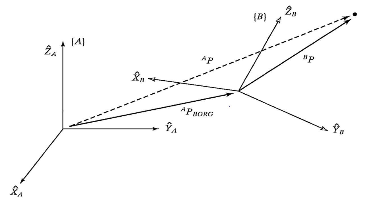
The basic theory of coordinate system transformation relationships is explained in every robotics textbook. It can be broken down into two parts: translation and rotation.It is described by a four-by-four matrix and the coordinate system is drawn in space. The transformation relationship between the two is actually the mathematical description of the vector.
The underlying principle of the TF function in ROS is to encapsulate these mathematical transformations. For detailed theoretical knowledge, you can refer to the robotics textbook. We mainly explain the use of the TF coordinate management system.
3. TF command line operation
Let’s first learn about a robot following algorithm based on a coordinate system through the example of two small turtles. For the convenience of demonstration, it is best to operate this course in a virtual machine
3.1. Installation environment
This example requires us to install the corresponding function package first
sudo apt install ros-foxy-turtle-tf2-py ros-foxy-tf2-toolssudo pip3 install transforms3d
3.2. Start up
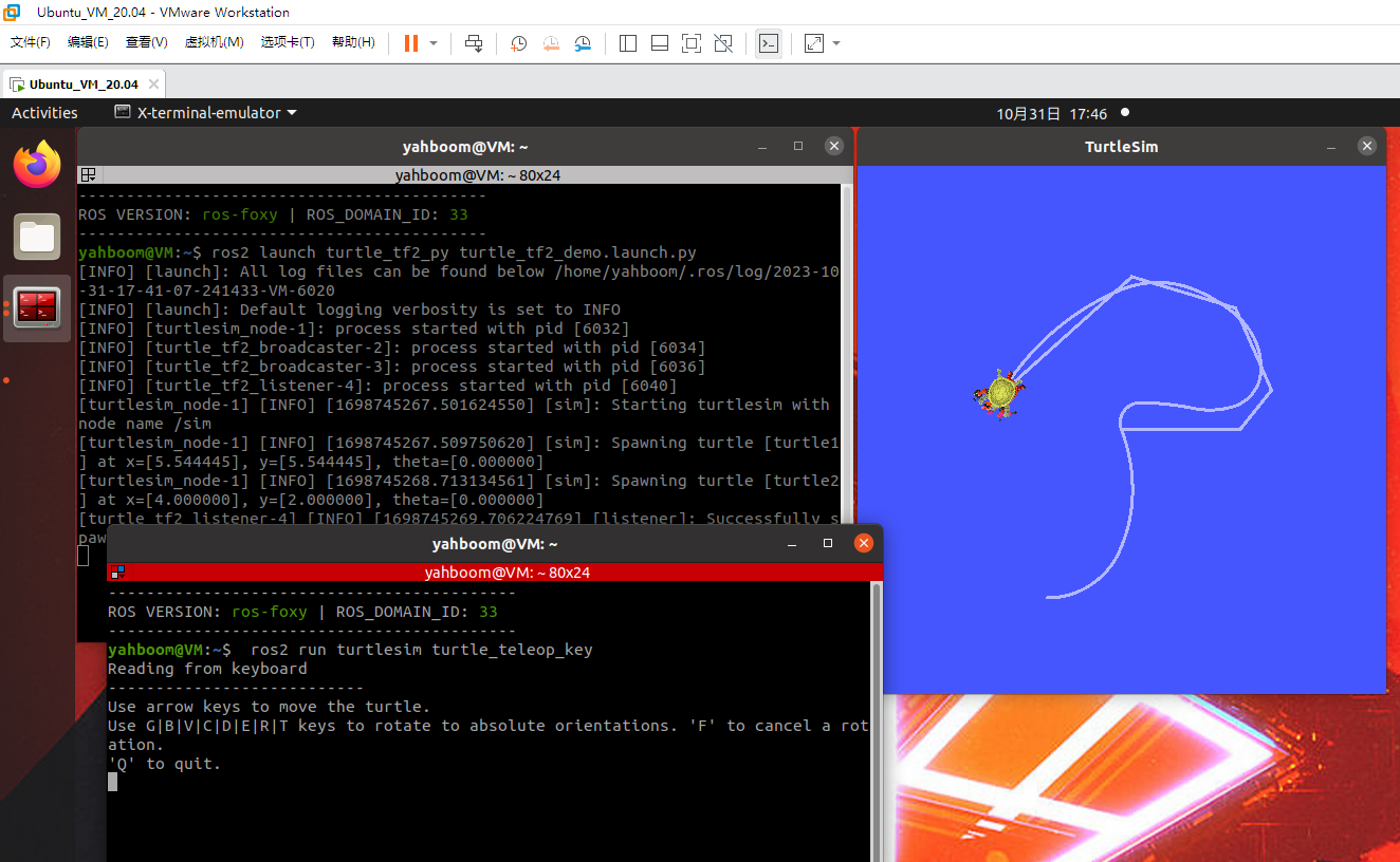
Then it can be started through a launch file, and then we can control one of the little turtles, and the other little turtle will automatically follow the movement.
xxxxxxxxxxros2 launch turtle_tf2_py turtle_tf2_demo.launch.pyros2 run turtlesim turtle_teleop_key
When we control the movement of one turtle, the other turtle will also follow.
3.3. View TF tree
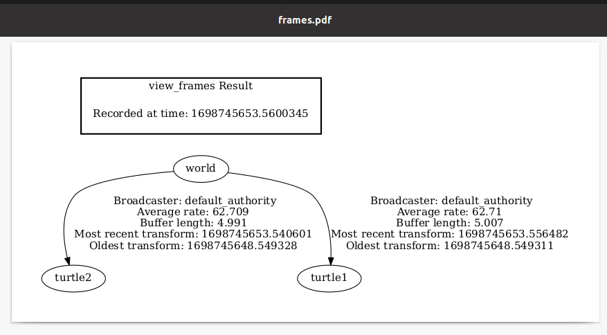
xxxxxxxxxxros2 run tf2_tools view_frames.py
By default, a frames.pdf file is generated in the current terminal path. After opening it, you can see the relationship between the various coordinate systems in the system.
3.4. Query coordinate transformation information
Just seeing the structure of the coordinate system is not enough. If we want to know the specific relationship between two coordinate systems, we can use the tf2_echo tool to view:
xxxxxxxxxxros2 run tf2_ros tf2_echo turtle2 turtle1
After the operation is successful, the terminal will print the transformation values of the coordinate system in a loop.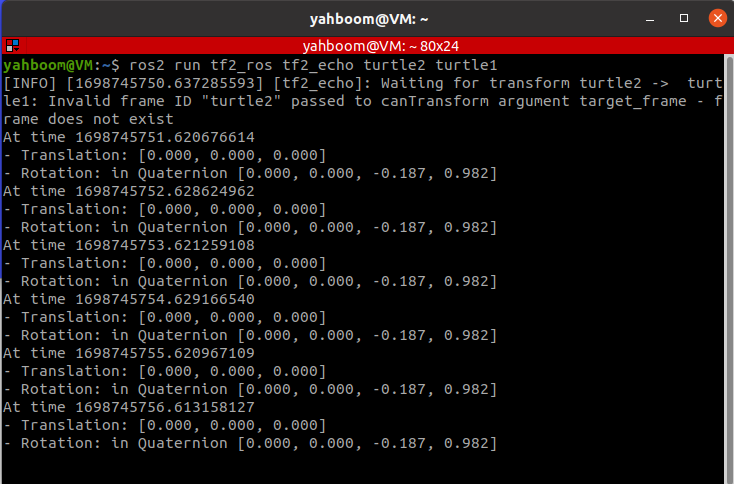
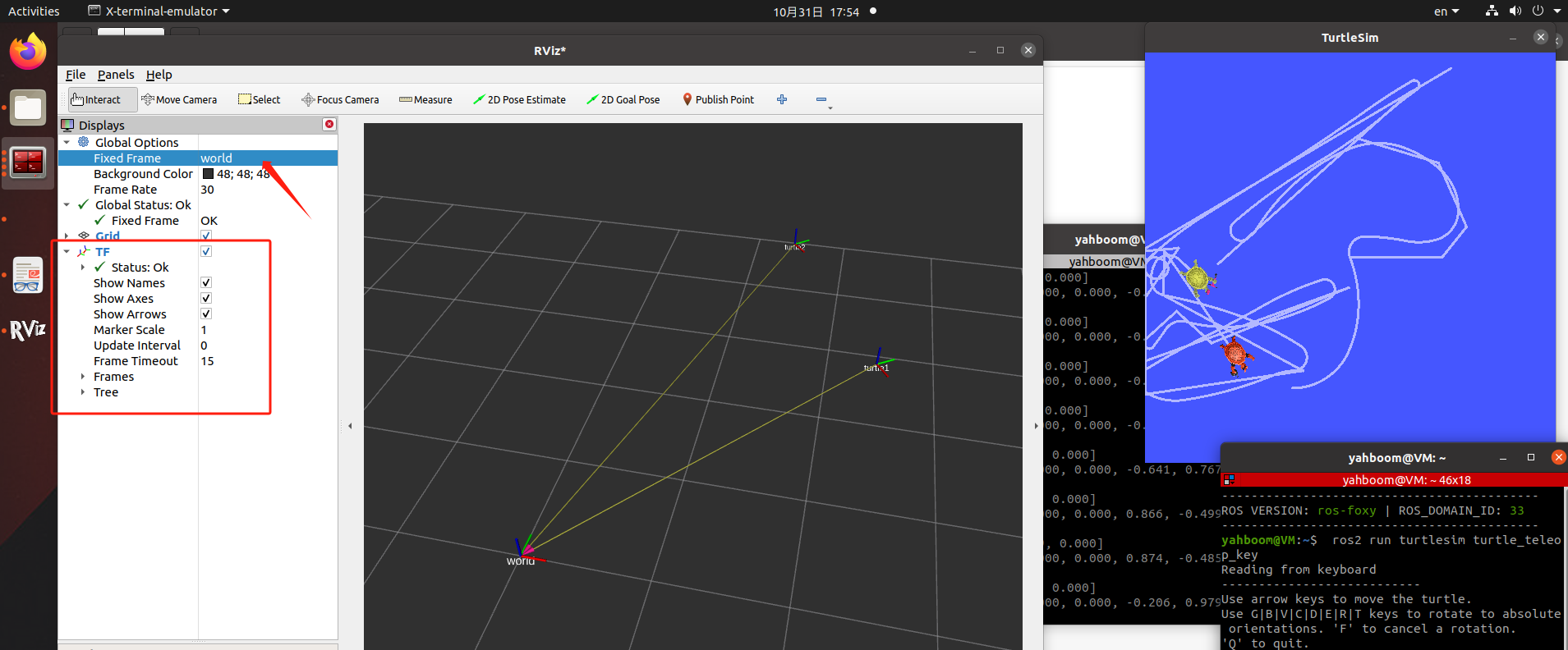
3.5. Coordinate system visualization
Use rviz2 for display:
xxxxxxxxxxrviz2
Set the reference coordinate system in rivz2 to: world, add TF display, and let the little turtle move, the coordinate axis in Rviz will start to move. Isn't this more intuitive!
4. Static coordinate transformation
The so-called static coordinate transformation means that the relative position between the two coordinate systems is fixed. For example, the position between radar and base_link is fixed.
Example: For the convenience of demonstration, it is best to operate this course in a virtual machine
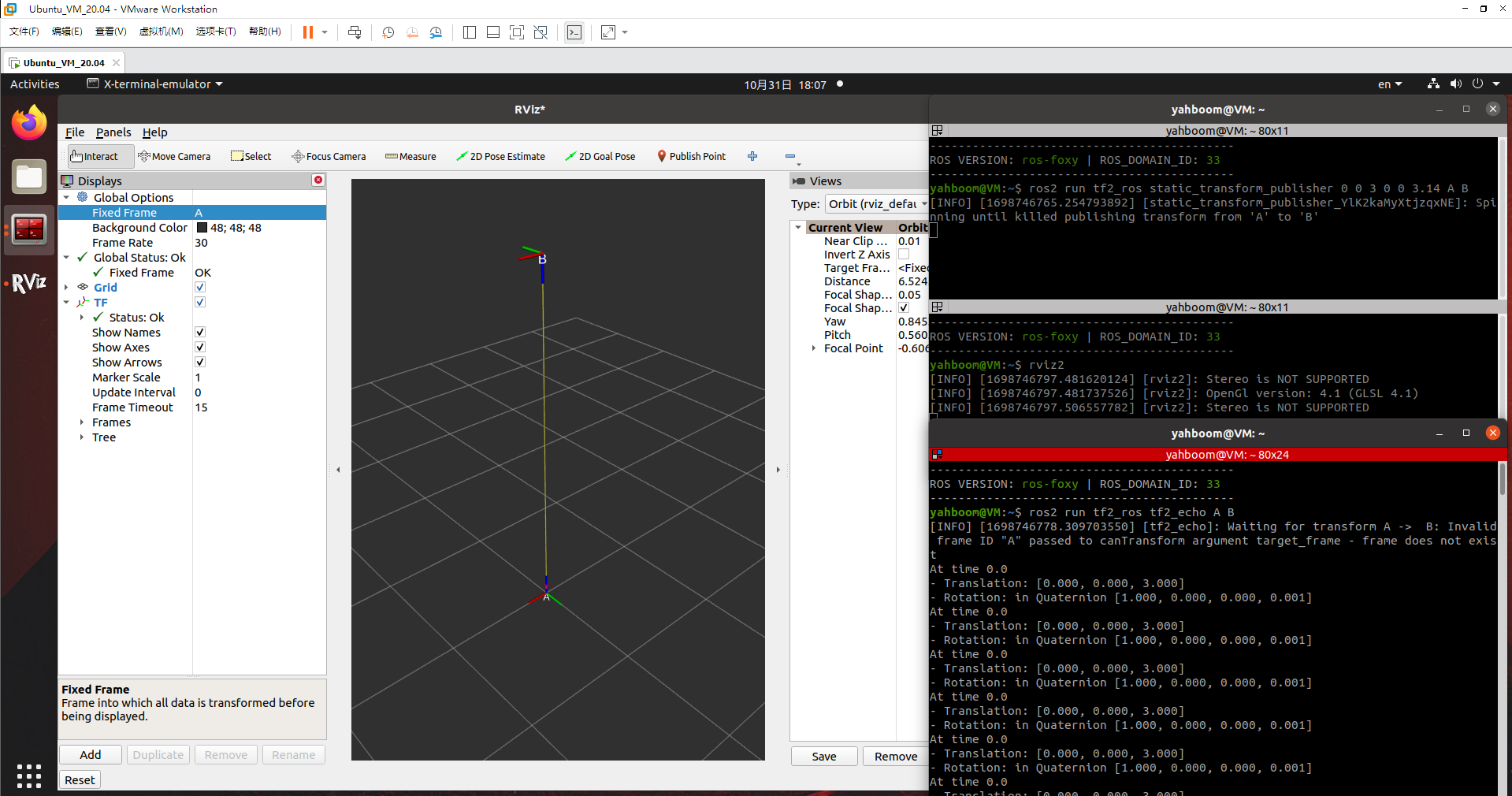
4.1. Release the poses from A to B
xxxxxxxxxxros2 run tf2_ros static_transform_publisher 0 0 3 0 0 3.14 A B4.2. Monitor/obtain TF relationship
xxxxxxxxxxros2 run tf2_ros tf2_echo A B
4.3. rivz visualization
5. Dynamic coordinate transformation
It will be explained in the next lesson, please see the next lesson