AT8236 2-Channel Motor Driver Module
1. Learning Objectives
Use AT8236 motor driver module to drive the motor.
2. Hardware connection
Pin connection between MSPM0G3507 and AT8236
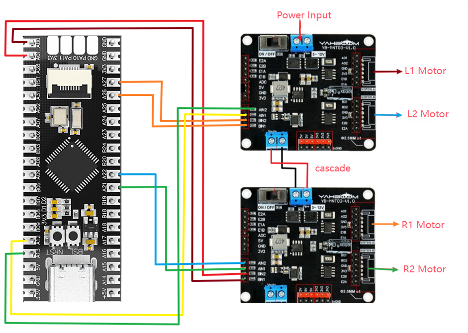
L1 motor:
| MSPM0G3507 | AT8236 |
|---|---|
| PA12 | AIN1 |
| PA13 | AIN2 |
L2 motor:
| MSPM0G3507 | AT8236 |
|---|---|
| PA26 | BIN1 |
| PA27 | BIN2 |
R1 motor:
| MSPM0G3507 | AT8236 |
|---|---|
| PA21 | AIN1 |
| PA22 | AIN2 |
R2 motor:
| MSPM0G3507 | AT8236 |
|---|---|
| PA0 | BIN1 |
| PA1 | BIN2 |
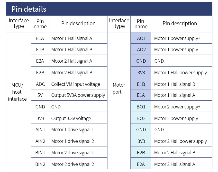
Motor and voltage regulator board pin connection:
| AT8236 | Motor |
|---|---|
| AO1 | Motor power + |
| AO2 | Motor power - |
AT8236 motor driver module voltage regulator board pin description:
3. Program description
- bsp_at8236.h
x#ifndef __BSP_TB6612_H_#define __BSP_TB6612_H_#include "ti_msp_dl_config.h"void init_motor(void);void L1_control(uint16_t motor_speed,uint8_t dir);void L2_control(uint16_t motor_speed,uint8_t dir);void R1_control(uint16_t motor_speed,uint8_t dir);void R2_control(uint16_t motor_speed,uint8_t dir);#endif
Define four motor control functions.
- bsp_at8236.c
xxxxxxxxxxvoid L1_control(uint16_t motor_speed,uint8_t dir){if(dir){DL_TimerA_setCaptureCompareValue(PWM_L1_INST, motor_speed, DL_TIMER_CC_0_INDEX);DL_TimerA_setCaptureCompareValue(PWM_L1_INST, 0, DL_TIMER_CC_1_INDEX);}else{DL_TimerA_setCaptureCompareValue(PWM_L1_INST, 0, DL_TIMER_CC_0_INDEX);DL_TimerA_setCaptureCompareValue(PWM_L1_INST, motor_speed, DL_TIMER_CC_1_INDEX);}}
The L1_control function is used to control the speed and direction of the L1 motor by adjusting the duty cycle of the PWM signal.
motor_speed and dir represent the motor speed and motor direction of the motor respectively.
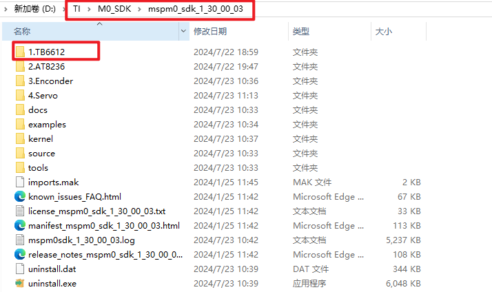
Note: The project source code must be placed in the SDK path for compilation,
For example, the path: D:\TI\M0_SDK\mspm0_sdk_1_30_00_03\TB6612