Serial port control servo
1. Learning objectives
Drive 180 degree servo through the serial port of 16-way servo driver board
2. Hardware connection
The servo used in this case is a 180 degree servo, which is connected to the S1 pin of the 16-way servo driver board
16-way servo driver board and MSPM0G3507 wiring
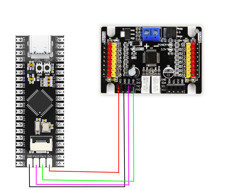
Note: The core board sold in this store has no solder pins at PA10 and PA11, which need to be soldered by yourself. Or change the serial port pin settings
3. Program description
- usart.h
x#ifndef __USART_H__#define __USART_H__#include "ti_msp_dl_config.h"void USART_Init(void);static void USART_SendData(unsigned char data);void UART_Servo(unsigned char servonum,unsigned char angle);#endif
Header file that defines serial port transmission data and serial port control functions
- usart.c
xxxxxxxxxxvoid USART_Init(void){// SYSCFG初始化// SYSCFG initializationSYSCFG_DL_init();//清除串口中断标志//Clear the serial port interrupt flagNVIC_ClearPendingIRQ(UART_0_INST_INT_IRQN);//使能串口中断//Enable serial port interruptNVIC_EnableIRQ(UART_0_INST_INT_IRQN);}//串口发送一个字节//The serial port sends a bytestatic void USART_SendData(unsigned char data){//当串口0忙的时候等待//Wait when serial port 0 is busywhile( DL_UART_isBusy(UART_0_INST) == true );//发送//sendDL_UART_Main_transmitData(UART_0_INST, data);}void UART_Servo(unsigned char servonum,unsigned char angle){servonum = 64 + servonum;date1 = angle/100 + 48;date2 = (angle%100)/10 + 48;date3 = angle%10 + 48;USART_SendData(0x24);//发送包头 Sending packet headerUSART_SendData(servonum);//发送舵机编号 Send servo numberUSART_SendData(date1);//发送角度 Send AngleUSART_SendData(date2);//发送角度 Send AngleUSART_SendData(date3);//发送角度 Send AngleUSART_SendData(0x23);//发送包尾 Sending packet taildelay_ms(100);}//串口的中断服务函数//Serial port interrupt service functionvoid UART_0_INST_IRQHandler(void){uint8_t receivedData = 0;//如果产生了串口中断//If a serial port interrupt occursswitch( DL_UART_getPendingInterrupt(UART_0_INST) ){case DL_UART_IIDX_RX://如果是接收中断 If it is a receive interrupt// 接收发送过来的数据保存 Receive and save the data sentreceivedData = DL_UART_Main_receiveData(UART_0_INST);// 检查缓冲区是否已满 Check if the buffer is fullif (recv0_length < RE_0_BUFF_LEN_MAX - 1){recv0_buff[recv0_length++] = receivedData;}else{recv0_length = 0;}// 标记接收标志 Mark receiving flagrecv0_flag = 1;break;default://其他的串口中断 Other serial port interruptsbreak;}}
Define the serial port initialization function, the function of sending a byte of data, the serial port interrupt service function, and the serial port data sending function to communicate with the 16-channel servo driver board to control the servo.
The value range of servonum is (1-16), and the value range of angle is (0-180).
- empty.c
xxxxxxxxxxint main(void){int i=0;USART_Init();while (1){for(i = 0;i<180;i+=5){UART_Servo(1,i);}UART_Servo(1,0);}}
Assign values to the serial port control function. Use loops to control the continuous change of the servo from 0 to 180 degrees.
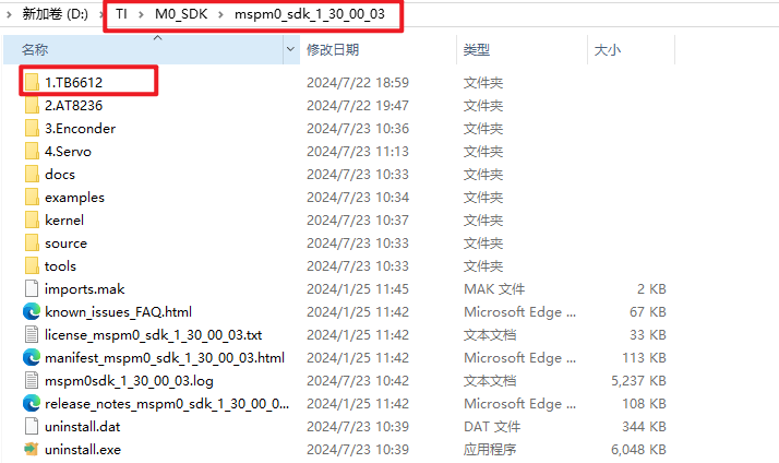
Note: The project source code must be placed in the SDK path for compilation.
For example, the path is: D:\TI\M0_SDK\mspm0_sdk_1_30_00_03\1.TB6612
4. Experimental phenomenon
Connect the servo to the S1 interface of the 16-channel servo driver board and burn the program to MSPM0G3507. After burning, connect the MSPM0G3507 to the 16-channel servo driver board according to the wiring diagram. After powering on, you will see the servo rotate from 0 to 180 degrees. Finally, return to 0 degrees, and repeat.