Expand self-driving car
1. Opening instructions
Please read the "Motor Introduction and Usage" in the four-way motor driver board information first to understand the motor parameters, wiring method, and power supply voltage you are currently using. To avoid burning the motherboard or motor.
Usage tips: Since the yaw angle of MPU6050 is easy to drift, or different motors are used, this project may not run perfectly on the track after burning. You can modify the variables according to some key points mentioned in the code analysis below, or replace the MPU6050 with other modules.
2. Experimental preparation
Wheeled car chassis V1 four-wheel drive version, 4*310 motors, 7.4V lithium battery, eight-way patrol module, MPU6050, MSPM0 robot expansion board (optional), MSPM0G3507 core board (Yahboom). The sound and light reminders required in question H are integrated on the MSPM0 robot expansion board (buzzer PB24) and the MSPM0G3507 core board (LED PB2). If the user does not use the MSPM0 robot expansion board, he needs to prepare a buzzer. And the question selection function button K1 (PA2) is located on the MSPM0 robot expansion board
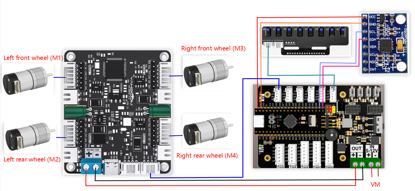
The relationship between the 4 motor interfaces and the car is as follows:
M1 -> upper left motor (left front wheel of the car)
M2 -> lower left motor (left rear wheel of the car)
M3 -> upper right motor (right front wheel of the car)
M4 -> lower right motor (right rear wheel of the car)
Hardware wiring:
Wiring using the mspm0 expansion board
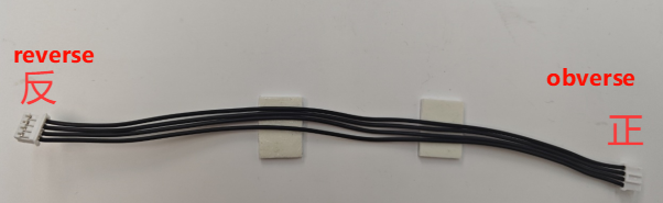
Note: The wire used for the eight-way patrol module and the wire used to connect the MSPM0 robot expansion board and the four-way motor drive module are: PH2.0-4pin cable, double-ended all black, reverse (200mm), the direction of the reverse cable holder is shown in the figure below
Use msp core board wiring
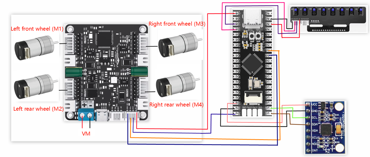
Wiring pins:
| Four-way motor driver board | MSPM0G3507 |
|---|---|
| RX2 | PB6 |
| TX2 | PB7 |
| GND | GND |
| 5V | 5V |
| Motor | Four-way motor driver board (Motor) |
|---|---|
| M2 | M- |
| V | 3V3 |
| A | H1B |
| B | H1A |
| G | GND |
| M1 | M+ |
| 8-channel patrol module | MSPM0G3507 |
|---|---|
| 5V | 5V |
| SCL | PA15 |
| SDA | PA16 |
| GND | GND |
| MPU6050 | MSPM0G3507 |
|---|---|
| VCC | 5V |
| GND | GND |
| SCL | PA1 |
| SDA | PA0 |
3. Key code analysis
According to the motor model you purchased, modify the beginning of empty.c to your own motor model, otherwise the car will easily get out of control when running.
- empty.c
x
//1:520电机 2:310电机 3:测速码盘TT电机 4:TT直流减速电机 5:L型520电机 //1:520 motor 2:310 motor 3:speed code disc TT motor 4:TT DC reduction motor 5:L type 520 motorMOTOR_TYPE: used to set the type of motor used. Modify the corresponding number according to the comments based on the motor you are currently using.
During the operation of MPU6050, angle deviation is prone to occur, and the encoder data of different motors will be different. So when running the competition question, you need to modify the variables of angle and mileage in the question.c file according to your own situation. Here, take question 3 as an example to explain some places that may need to be modified
- question.c
xxxxxxxxxxvoid Question_Task_3(void){ if(q3_first_flag == 0) { //记录第一次发车的角度 Record the angle of the first departure first_angle = calibratedYaw; //开始计算里程数 Start calculating mileage encoder_odometry_flag = 1; //声光提示 Sound and light prompts bee_time = 300; //开始问题3的小状态机 Start the small state machine of problem 3 State_Machine.Q3_State = Q3_STATE_1; q3_first_flag = 1; } if(State_Machine.Q3_State == Q3_STATE_1) { //设定斜切目标角度 Set the beveled target angle object_angle = navigetion_0_360_limit(first_angle + 32); Motion_Car_Control(300,0,0); Angle_error = get_minor_arc(object_angle,calibratedYaw); PID_Value = Dir_PID(Angle_error); Motion_Yaw_Calc(PID_Value); if(LineCheck() == BLACK && odometry_sum >= 1000) { bee_time = 300; //停止计算里程数并清零 Stop calculating mileage and clear encoder_odometry_flag = 0; odometry_sum = 0; //进入问题3的下一个状态 Enter the next state of question 3 State_Machine.Q3_State = Q3_STATE_2; } } else if(State_Machine.Q3_State == Q3_STATE_2) //问题3的状态2(左转灰度循迹) State 2 of question 3 (left turn grayscale tracking) { LineWalking(); //检测到白线,同时角度在设定的范围内时,进入下一个状态 When the white line is detected and the angle is within the set range, it enters the next state if((calibratedYaw < 220 && calibratedYaw > 150) && LineCheck() == WHITE) { bee_time = 300; State_Machine.Q3_State = Q3_STATE_3; } } else if(State_Machine.Q3_State == Q3_STATE_3) { static int Q3_state3_first_flag = 0; if(Q3_state3_first_flag == 0) { //设定斜切目标角度 Set the beveled target angle object_angle =navigetion_0_360_limit(first_angle + 180) - 11; Q3_state3_first_flag = 1; } Motion_Car_Control(300,0,0); //开始计算里程数 Start calculating mileage encoder_odometry_flag = 1; Angle_error = get_minor_arc(object_angle,calibratedYaw); PID_Value = Dir_PID(Angle_error); Motion_Yaw_Calc(PID_Value); //检测到黑线,并且里程计数值大于等于1200时进入下一个状态 When the black line is detected and the mileage count value is greater than or equal to 1200, enters the next state if(odometry_sum >= 1200 && LineCheck() == BLACK) { //停止计算里程数并清零 Stop calculating mileage and clear encoder_odometry_flag = 0; odometry_sum = 0; bee_time = 300; Q3_state3_first_flag = 0; State_Machine.Q3_State = Q3_STATE_4; } } else if(State_Machine.Q3_State == Q3_STATE_4) { LineWalking(); //检测到白线,同时角度在设定的范围内时,进入下一个状态 When the white line is detected and the angle is within the set range, it enters the next state if((calibratedYaw > 325 || calibratedYaw < 90) && LineCheck() == WHITE) { bee_time = 300; State_Machine.Q3_State = Q3_STATE_5; } } else { //退出当前题目 Exit the current question State_Machine.Q3_State = STOP_STATE; State_Machine.Main_State = STOP_STATE; //问题3的运行标志位清零 The running flag bit of question 3 is cleared q3_first_flag = 0; }}In Q3_STATE_1: object_angle = navigetion_0_360_limit(first_angle + 32); sets the angle to which the car should rotate when running, which is the starting angle + 32°. If 32° cannot reach the corresponding point when running, modify the number 32 according to the offset of your car.
if(LineCheck() == BLACK && odometry_sum >= 1000) here uses the eight-way line inspection sensor to detect whether it has reached the black line and whether the mileage count is greater than or equal to 1000. If the track conditions are not good and the eight-way line inspection sensor is accidentally touched, resulting in entering the next state in advance, you can increase odometry_sum.
In Q3_STATE_2: if((calibratedYaw < 220 && calibratedYaw > 150) && LineCheck() == WHITE), the angle transmitted by MPU6050 is used to determine whether the robot is in the range of 150°-220° and has reached the white background area. However, sometimes when the robot reaches this point, the angle may exceed this range, causing the robot to be unable to enter the next state. At this time, you can choose to modify the angle value here. The specific modification requires actual measurement.
- empty.c
xxxxxxxxxx//1:520电机 2:310电机 3:测速码盘TT电机 4:TT直流减速电机 5:L型520电机 //1:520 motor 2:310 motor 3:speed code disc TT motor 4:TT DC reduction motor 5:L type 520 motorint main(void){ USART_Init();//打印串口初始化、四路电机通信串口初始化 Print serial port initialization, four-channel motor communication serial port initialization //设置电机类型 Set motor type Set_Motor(MOTOR_TYPE); send_upload_data(false,true,false);delay_ms(10); /*MPU6050初始化 MPU6050 Initialization*/ MPU6050_Init(); //DMP初始化 DMP Initialization while( mpu_dmp_init() ) { printf("dmp error\r\n"); delay_ms(200); } //蜂鸣器初始化 Buzzer initialization PWM_Buzzer_Init(); //问题状态机初始化 Problem state machine initialization State_Machine_init(); //清除定时器中断标志 Clear timer interrupt flag NVIC_ClearPendingIRQ(TIMER_0_INST_INT_IRQN); //使能定时器中断 Enable Timer Interrupt NVIC_EnableIRQ(TIMER_0_INST_INT_IRQN); //定时器开始计时 Timer start DL_TimerA_startCounter(TIMER_0_INST); //初始化成功后,LED灯快闪两下,蜂鸣器快响两下 After the initialization is successful, the LED light flashes twice, and the buzzer rings twice int i = 0; for(i=0;i<4;i++) { LED2_Toggle(); Buzzer_Toggle(); delay_ms(100); } while(1) { Scheduler_Run();//开始运行任务调度器 Start running the task scheduler //题目选择判断 Question selection judgment if(g_LinePortal_flag) { switch(State_Machine.Main_State) { case STOP_STATE: Contrl_Pwm(0,0,0,0); break; case QUESTION_1://赛题1 Question 1 Question_Task_1(); break; case QUESTION_2://赛题2 Question 2 Question_Task_2(); break; case QUESTION_3://赛题3 Question 3 Question_Task_3(); break; case QUESTION_4://赛题4 Question 4 Question_Task_4(); break; default: break; } } } }First initialize all peripherals. If successful, the LED light will flash twice and the buzzer will sound twice. Then run the task scheduler to obtain the required data in sequence. In the while loop, continue to determine whether the competition topic is selected by pressing the button.
- MOTOR_TYPE: Change to the motor type you are using
- app_motor.c
xxxxxxxxxxvoid Set_Motor(int MOTOR_TYPE){ if(MOTOR_TYPE == 1) { send_motor_type(1);//配置电机类型 Configure motor type delay_ms(100); send_pulse_phase(30);//配置减速比 查电机手册得出 Configure the reduction ratio. Check the motor manual to find out delay_ms(100); send_pulse_line(11);//配置磁环线 查电机手册得出 Configure the magnetic ring wire. Check the motor manual to get the result. delay_ms(100); send_wheel_diameter(67.00);//配置轮子直径,测量得出 Configure the wheel diameter and measure it delay_ms(100); send_motor_deadzone(1900);//配置电机死区,实验得出 Configure the motor dead zone, and the experiment shows delay_ms(100); } else if(MOTOR_TYPE == 2) { send_motor_type(2); delay_ms(100); send_pulse_phase(20); delay_ms(100); send_pulse_line(13); delay_ms(100); send_wheel_diameter(48.00); delay_ms(100); send_motor_deadzone(1600); delay_ms(100); } else if(MOTOR_TYPE == 3) { send_motor_type(3); delay_ms(100); send_pulse_phase(45); delay_ms(100); send_pulse_line(13); delay_ms(100); send_wheel_diameter(68.00); delay_ms(100); send_motor_deadzone(1600); delay_ms(100); } else if(MOTOR_TYPE == 4) { send_motor_type(4); delay_ms(100); send_pulse_phase(48); delay_ms(100); send_motor_deadzone(1000); delay_ms(100); } else if(MOTOR_TYPE == 5) { send_motor_type(1); delay_ms(100); send_pulse_phase(40); delay_ms(100); send_pulse_line(11); delay_ms(100); send_wheel_diameter(67.00); delay_ms(100); send_motor_deadzone(1900); delay_ms(100); }}This function is used to store the parameters of the motors sold in our store. By modifying the MOTOR_TYPE parameter at the beginning of empty.c, one-click configuration can be achieved. Under normal circumstances, do not modify the code here when using the motors of our store. If you use your own motor, you can select any motor and change the parameters to the parameters of the motor you use. If you do not understand the meaning of these parameters, you can refer to the document "4-way motor driver board control instructions" to understand the specific meaning of each instruction.
4. Experimental phenomenon
After the car is powered on. The peripherals used will be initialized. You need to wait for a while. After the initialization is successful, the LED will flash twice quickly, and the buzzer will beep twice quickly. Then you can press and hold the K1 button on the expansion board to select the competition question. If you hear a beep, it is the first question, and if you hear two beeps, it is the second question, and so on. After selecting the question, press the K1 button again to start the task. The buzzer will beep for a long time, and then start the task.