FPIOA Pinout
Preface
The pins of K230 support FPIOA (Field Programmable Input and Output Array)
FPIOA can be simply understood as allowing a certain pin on the K230 to be multiplexed into multiple functions such as uart, iic, pwm, etc. at the hardware level.
FPIOA (also called IOMUX) mainly configures the functions of physical PADs (pins). Since SoCs have many functions but few pins (pads), multiple functions share the same I/O pins (pads), but a pad can only use one function at a time, so IOMUX is needed for function selection.
Note: This section mainly introduces the theory and operation of FPIOA. When studying the actual chapters later, we can more directly experience the actual usage and function of FPIOA.
FPIOA Common Methods
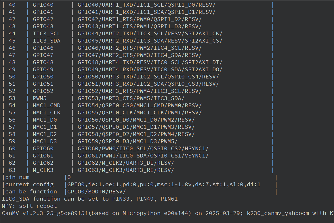
The source code is located in [Source Code/02.Basic/01.fpioa.py] and execute the following code
from machine import FPIOA# Instantiate FPIOAfpioa = FPIOA ()# Print all pin configurationsfpioa.help ( )# Print the detailed configuration of the specified pinfpioa.help ( 0 )# Print all available configuration pins for the specified functionfpioa . help ( FPIOA . IIC0_SDA , func = True )# Get the pin where the specified function is currently locatedfpioa . get_pin_num ( FPIOA . UART0_TXD )# Get the current function of the specified pinfpioa.get_pin_func ( 0 )You can see that in the serial terminal, all the IO ports of the K230 chip and the functions that support multiplexing are output
YAHBOOM K230 Pinout
In order to reduce the size of the module, our K230 module does not bring out all the pins supported by the chip. Let's take a look at some of the commonly used pins of YAHBOOM K230
Two rows of pins next to the heat sink
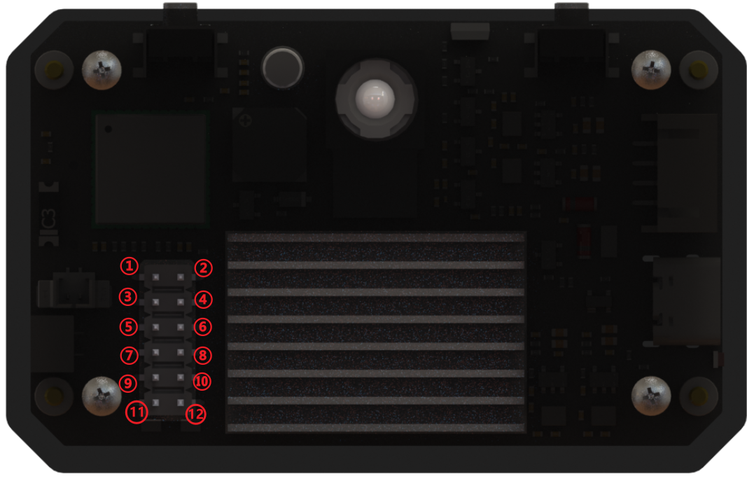
1: GPIO 42, can be reused as: GPIO42 / UART1_RTS / PWM0 / QSPI1_D2 / RESV /
2: GPIO 43, can be reused as: GPIO43 / UART1_CTS / PWM1 / QSPI1_D3 / RESV /
3: GPIO 33, can be reused as: GPIO33 / IIC0_SDA / IIS_WS / UART3_RXD / RESV /
4: GND
5: GPIO 32, can be reused as: GPIO32 / IIC0_SCL / IIS_CLK / UART3_TXD / RESV /
6: GPIO 26, can be reused as: GPIO26 / MMC1_CLK / RESV / PDM_CLK /
7: GND
8: GPIO 34, can be reused as: GPIO34 / IIC1_SCL / IIS_D_IN0 / PDM_IN3 / UART3_RTS /
9: 5v output
10: GPIO 35, can be reused as: GPIO35 / IIC1_SDA / IIS_D_OUT0 / PDM_IN1 / UART3_CTS /
11: 5v output
12: 3.3v output
!!! When connecting the 12-pin GPIO, please be sure to confirm the silk-screen mark to ensure the correct connection. We will not provide after-sales repair service for man-made damage caused by short circuit, reverse connection, overvoltage or overcurrent. !!!
Communication interface next to the USB port
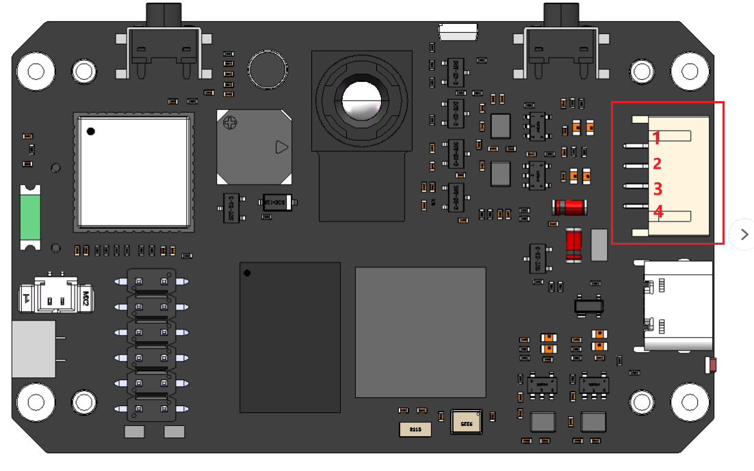
1: 5v
2: GND
3: UART1_TXD | Can be reused as GPIO9 / PWM4 / UART1_TXD / IIC1_SCL / RESV/
4: UART1_RXD | Can be reused as GPIO10 / CTRL_IN_3D / UART1_RXD / IIC1_SDA / RESV/
The communication interface defaults to serial port UART1. The initialization code in the YbUart module is as follows
x
fpioa.set_function(9, fpioa.UART1_TXD, ie=0, oe=1)fpioa.set_function(10, fpioa.UART1_RXD, ie=1, oe=0)uart = UART(UART.UART1, baudrate)
- For the complete official documentation of FPIOA, please refer to 2.8 FPIOA Module API Manual — CanMV K230