MSPM0 color follower
MSPM0 color follower1. Opening instructions2. Experimental preparationThe relationship between the 4 motor interfaces and the car is as follows:Hardware wiringWiring using MSPM0 robot expansion boardWiring using MSPM0G3507 core board (Yahboom)Wiring pins3. Key code analysis4. Experimental operation5. Experimental phenomenon
1. Opening instructions
Please read the "Motor Introduction and Usage" in the four-way motor driver board information first to understand the motor parameters, wiring method, and power supply voltage you are currently using. To avoid burning the motherboard or motor.
Motor: The case and code take the 520L motor of our store as an example.
2. Experimental preparation
National race chassis V2 four-wheel drive version, 4*L520 motor, 12V lithium battery, K210 vision module, MSPM0 robot expansion board (optional), MSPM0G3507 core board (Yahboom).
The relationship between the 4 motor interfaces and the car is as follows:
M1 -> upper left motor (left front wheel of the car)
M2 -> lower left motor (left rear wheel of the car)
M3 -> upper right motor (right front wheel of the car)
M4 -> lower right motor (right rear wheel of the car)
Hardware wiring
Wiring using MSPM0 robot expansion board
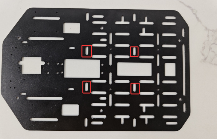
During the installation and wiring process, if the wiring length is not enough, you can move the MSPM0 robot expansion board forward a little and install it, as shown in the following figure.
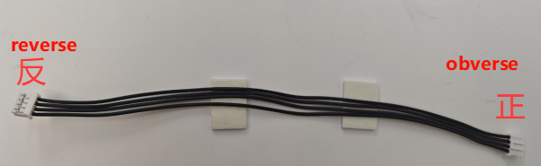
Note: The wire used for the k210 vision module and the wire used to connect the MSPM0 robot expansion board and the four-way motor driver module are: PH2.0-4pin cable, double-ended all black, reverse (200mm), the direction of the reverse cable holder is shown in the following figure
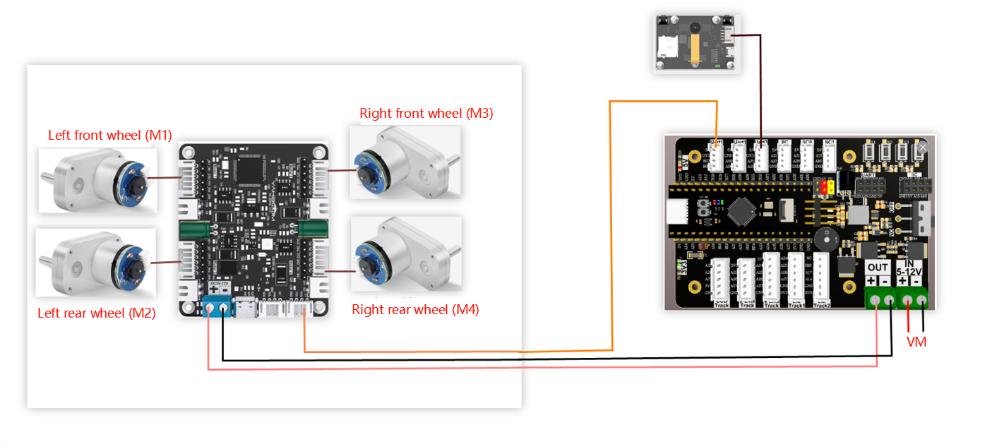
Wiring using MSPM0G3507 core board (Yahboom)
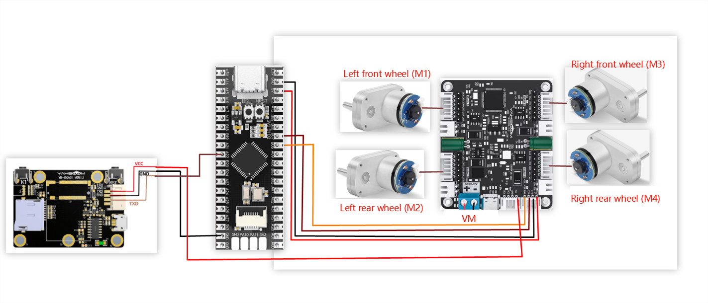
Wiring pins
| Four-way motor driver board | MSPM0G3507 core board (Yahboom) |
|---|---|
| RX2 | PB6 |
| TX2 | PB7 |
| GND | GND |
| 5V | 5V |
Take M1 motor as an example below, and other motors are similar
| Motor | Four-way motor driver board (Motor) |
|---|---|
| M+ | M1+ |
| M- | M1- |
| GND | GND |
| VCC | 3V3 |
| B | H1A |
| A | H1B |
| K210 vision module | MSPM0G3507 core board (Yahboom) |
|---|---|
| 5V | 5V |
| GND | GND |
| TXD | PA22 |
| RXD | PA21 |
3. Key code analysis
- revaction.c
x// 获取命令标志 Get command flaguint8_t Get_CMD_Flag(void){ return New_CMD_flag;}// 清除命令数据和相关标志 Clear command data and related flagsvoid Clear_CMD_Flag(void){ for (uint8_t i = 0; i < New_CMD_length; i++) { RxBuffer[i] = 0; } New_CMD_length = 0; New_CMD_flag = 0;}//数据分析 data analysisvoid Upper_Data_Parse(uint8_t *data_buf, uint8_t num){ uint8_t func_id = *(data_buf + 3); switch (func_id) { /* 判断功能字:小车速度设置 Judgment function word: Trolley speed setting */ case FUNC_MOTION: { uint8_t parm = (uint8_t) *(data_buf + 4); int16_t Vx_recv = *(data_buf + 6) << 8 | *(data_buf + 5); int16_t Vy_recv = *(data_buf + 8) << 8 | *(data_buf + 7); int16_t Vz_recv = *(data_buf + 10) << 8 | *(data_buf + 9); uint8_t adjust = parm & 0x80; if (Vx_recv == 0 && Vy_recv == 0 && Vz_recv == 0) { Contrl_Pwm(0,0,0,0); } else { Motion_Car_Control(Vx_recv, Vy_recv, Vz_recv, (adjust==0?0:1)); } break; } /* 判断功能字:彩灯控制 Judgment function word: color light control */ case FUNC_RGB: { u8 index = *(data_buf + 4); u8 red = *(data_buf + 5); u8 green = *(data_buf + 6); u8 blue = *(data_buf + 7);// printf("RED:%d, G:%d, B:%d\r\n",red,green,blue); RGB_Set_Color(index, red, green, blue); RGB_Update(); break; } default: break; }}//数据接收并保存 Data received and savedvoid Upper_Data_Receive(uint8_t Rx_Temp){ switch (RxFlag) { case 0: if (Rx_Temp == PTO_HEAD) { RxBuffer[0] = PTO_HEAD; RxFlag = 1; } break; case 1: if (Rx_Temp == PTO_DEVICE_ID) { RxBuffer[1] = PTO_DEVICE_ID; RxFlag = 2; RxIndex = 2; } else { RxFlag = 0; RxBuffer[0] = 0x0; } break; case 2: New_CMD_length = Rx_Temp + 2; if (New_CMD_length >= PTO_MAX_BUF_LEN) { RxIndex = 0; RxFlag = 0; RxBuffer[0] = 0; RxBuffer[1] = 0; New_CMD_length = 0; break; } RxBuffer[RxIndex] = Rx_Temp; RxIndex++; RxFlag = 3; break; case 3: RxBuffer[RxIndex] = Rx_Temp; RxIndex++; if (RxIndex >= New_CMD_length) { New_CMD_flag = 1; RxIndex = 0; RxFlag = 0; } break; default: break; }}Get_CMD_Flag: Get the k210 data flag
Clear_CMD_Flag: Clear command data and related flags
Upper_Data_Parse: Parse the saved k210 data and determine the function of k210
Upper_Data_Receive: Save the received k210 data
- app_motor.c
xxxxxxxxxx// 返回当前小车轮子轴间距和的一半 Returns half of the sum of the axle spacings of the current trolley wheels.static float Motion_Get_APB(void){ return Car_APB;}void Set_Motor(int MOTOR_TYPE){ if(MOTOR_TYPE == 1) { send_motor_type(1);//配置电机类型 Configure motor type delay_ms(100); send_pulse_phase(30);//配置减速比 查电机手册得出 Configure the reduction ratio. Check the motor manual to find out delay_ms(100); send_pulse_line(11);//配置磁环线 查电机手册得出 Configure the magnetic ring wire. Check the motor manual to get the result. delay_ms(100); send_wheel_diameter(67.00);//配置轮子直径,测量得出 Configure the wheel diameter and measure it delay_ms(100); send_motor_deadzone(1900);//配置电机死区,实验得出 Configure the motor dead zone, and the experiment shows delay_ms(100); } ... else if(MOTOR_TYPE == 5) { send_motor_type(1); delay_ms(100); send_pulse_phase(40); delay_ms(100); send_pulse_line(11); delay_ms(100); send_wheel_diameter(67.00); delay_ms(100); send_motor_deadzone(1900); delay_ms(100); }}void Motion_Car_Control(int16_t V_x, int16_t V_y, int16_t V_z, uint8_t adjust){ float robot_APB = Motion_Get_APB(); speed_lr = 0; speed_fb = V_x; speed_spin = (V_z / 1000.0f) * robot_APB; if (V_x == 0 && V_y == 0 && V_z == 0) { Contrl_Speed(0,0,0,0); return; } speed_L1_setup = speed_fb - speed_spin; speed_L2_setup = speed_fb - speed_spin; speed_R1_setup = speed_fb + speed_spin; speed_R2_setup = speed_fb + speed_spin; if (speed_L1_setup > 1000) speed_L1_setup = 1000; if (speed_L1_setup < -1000) speed_L1_setup = -1000; if (speed_L2_setup > 1000) speed_L2_setup = 1000; if (speed_L2_setup < -1000) speed_L2_setup = -1000; if (speed_R1_setup > 1000) speed_R1_setup = 1000; if (speed_R1_setup < -1000) speed_R1_setup = -1000; if (speed_R2_setup > 1000) speed_R2_setup = 1000; if (speed_R2_setup < -1000) speed_R2_setup = -1000; // printf("%d\t,%d\t,%d\t,%d\r\n",speed_L1_setup,speed_L2_setup,speed_R1_setup,speed_R2_setup); Contrl_Speed(speed_L1_setup, speed_L2_setup, speed_R1_setup, speed_R2_setup); }Motion_Get_APB: Returns half of the current wheel axle spacing of the car
Set_Motor: Sets the motor type of the four-way motor driver board, and changes the motor type according to your actual situation
Motion_Car_Control: Controls the different motion states of the car
- app_motor_usart.c
xxxxxxxxxx//发送电机类型 Transmitter motor typevoid send_motor_type(motor_type_t data){ sprintf((char*)send_buff,"$mtype:%d#",data); Send_Motor_ArrayU8(send_buff, strlen((char*)send_buff)); }//发送电机死区 Send motor dead zonevoid send_motor_deadzone(uint16_t data){ sprintf((char*)send_buff,"$deadzone:%d#",data); Send_Motor_ArrayU8(send_buff, strlen((char*)send_buff));}//发送电机磁环脉冲 Send motor magnetic ring pulsevoid send_pulse_line(uint16_t data){ sprintf((char*)send_buff,"$mline:%d#",data); Send_Motor_ArrayU8(send_buff, strlen((char*)send_buff));}//发送电机减速比 Transmitting motor reduction ratiovoid send_pulse_phase(uint16_t data){ sprintf((char*)send_buff,"$mphase:%d#",data); Send_Motor_ArrayU8(send_buff, strlen((char*)send_buff));}//发送轮子直径 Send wheel diametervoid send_wheel_diameter(float data){ sprintf((char*)send_buff,"$wdiameter:%.3f#",data); Send_Motor_ArrayU8(send_buff, strlen((char*)send_buff)); }//控制速度 Controlling Speedvoid Contrl_Speed(int16_t M1_speed,int16_t M2_speed,int16_t M3_speed,int16_t M4_speed){ sprintf((char*)send_buff,"$spd:%d,%d,%d,%d#",M1_speed,M2_speed,M3_speed,M4_speed); UART_Console_write(send_buff, strlen((char*)send_buff));// Send_Motor_ArrayU8(send_buff, strlen((char*)send_buff));}//控制pwm Control PWMvoid Contrl_Pwm(int16_t M1_pwm,int16_t M2_pwm,int16_t M3_pwm,int16_t M4_pwm){ sprintf((char*)send_buff,"$pwm:%d,%d,%d,%d#",M1_pwm,M2_pwm,M3_pwm,M4_pwm); UART_Console_write(send_buff, strlen((char*)send_buff));// Send_Motor_ArrayU8(send_buff, strlen((char*)send_buff));} Configure motor parameters
Contrl_Speed: Control the speed of 4 motors separately
Contrl_Pwm: Control 4 motors separately through PWM.
- empty.c
xxxxxxxxxx//1:520电机 2:310电机 3:测速码盘TT电机 4:TT直流减速电机 5:L型520电机 //1:520 motor 2:310 motor 3:speed code disc TT motor 4:TT DC reduction motor 5:L type 520 motorint main(void){ USART_Init(); printf("please wait...\r\n"); //使能DMA通道 Enable DMA Channel NVIC_ClearPendingIRQ(UART_1_INST_INT_IRQN); DL_DMA_enableChannel(DMA, DMA_CH0_CHAN_ID); NVIC_EnableIRQ(UART_1_INST_INT_IRQN); //开启与K210串口通信的中断 Enable interrupts for communication with the K210 serial port NVIC_ClearPendingIRQ(UART_2_INST_INT_IRQN); NVIC_EnableIRQ(UART_2_INST_INT_IRQN); //设置电机类型 Set motor type Set_Motor(MOTOR_TYPE); printf("Initialization Succeed\r\n"); while(1) { if (Get_CMD_Flag()) { Upper_Data_Parse(Get_RxBuffer(), Get_CMD_Length()); Clear_CMD_Flag(); } }}MOTOR_TYPE: used to set the type of motor used. Modify the corresponding number according to the comments based on the motor you are currently using.
USART_Init: Initialize the serial port for communication with the four-way motor driver board
Get_CMD_Flag: Start receiving data from k210
Upper_Data_Parse: Parse the received data from k210. And judge the function
Clear_CMD_Flag: Clear the received data and related flags
4. Experimental operation
- Burn the program to MSPM0.
- Download the car drive library and PID control library in the K210\library directory to the root directory of the memory card in advance.
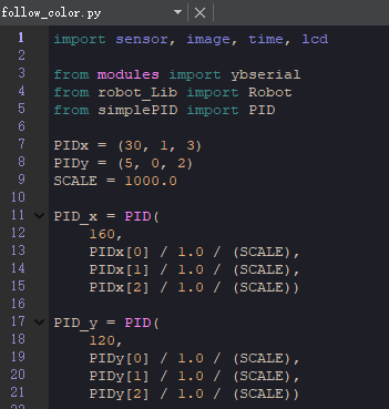
- Open CanMV IDE and download the follow_color.py code into the K210 module.
- Connect all the wires of the car.
- Put the car into the map of the visual patrol line, move the K210 module bracket to a suitable angle, and turn on the switch of the car.
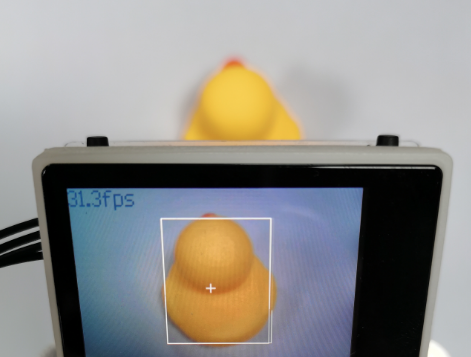
- After waiting for the system to initialize, the LCD displays the camera screen, and there is a white box in the middle of the screen. Please move the car to fill the white box with the color to be identified, and wait for the white box to turn green to start collecting colors. After the collection is completed, the green box disappears and the program starts running.
5. Experimental phenomenon
After waiting for the system to initialize, the LCD displays the camera image, and there is a white box in the middle of the screen. Please put the color to be identified in the white box, wait for the white box to turn green to start collecting colors, and the green box disappears after the collection is completed, and the program starts running.
The car will move with the color identified by the green box in the previous step. When the color is far away from the car, the car moves forward, when the color is close to the car, the car moves backward, and when the color moves to the left/right, the car also moves to the left/right, so that the identified color remains in the middle of the screen.
If you find that the car often cannot follow the object, please place a solid color object on the white background for the car to follow. If the problem is that the car reacts too slowly or too quickly, you can adjust the values of PID_x and PID_y appropriately.