Adjust potentiometer
Adjust potentiometer1.Learning objectives2.Sensor Wiring3.Programming3.1 Adding extension packages3.2 Building blocks used3.3 Combination building blocks4.Experimental phenomenon
1.Learning objectives
In this course, we mainly learn how to display the potentiometer status through MakeCode graphical programming.
2.Sensor Wiring
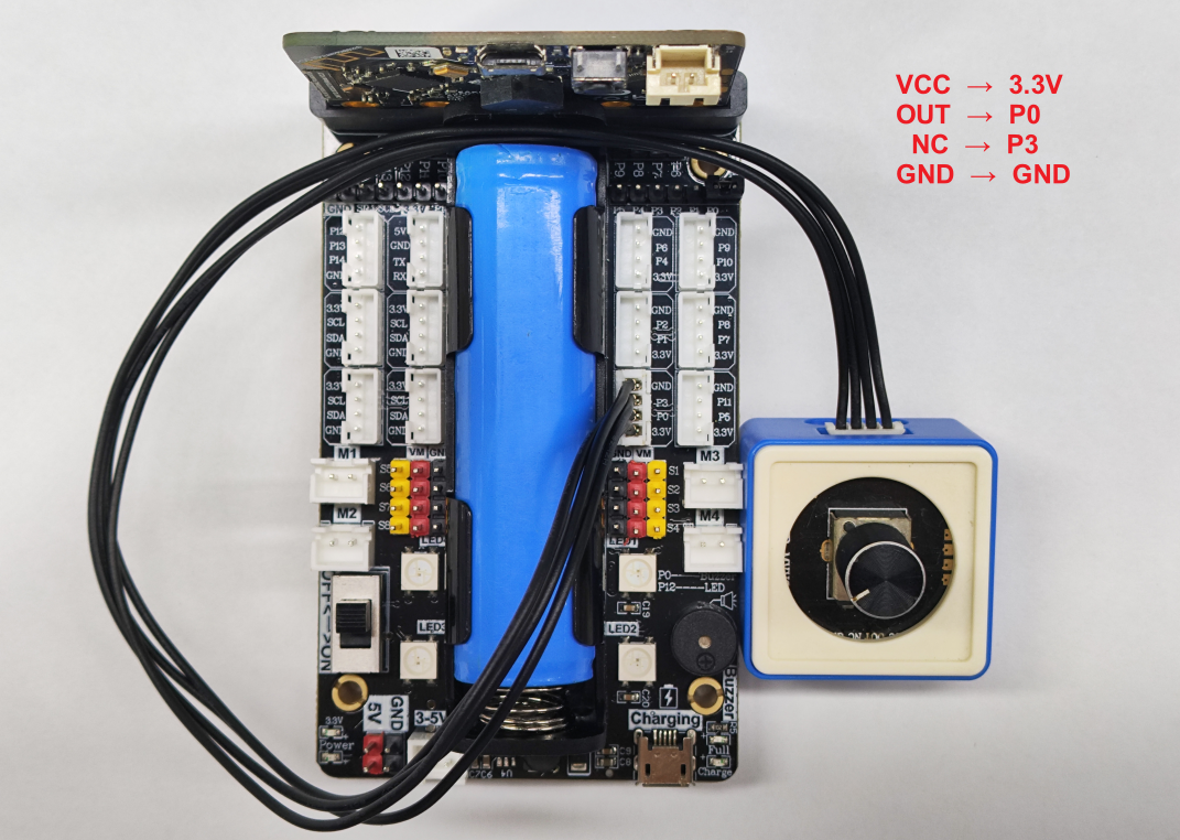
The potentiometer is connected to the P0P3 pin.
3.Programming
Method 1: Online programming:
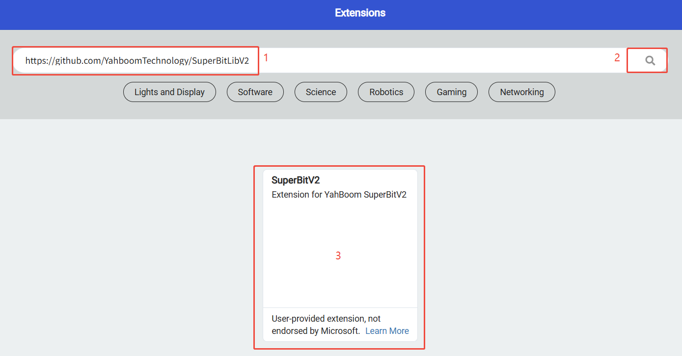
First, connect micro:bit to the computer via a USB cable. A USB flash drive will pop up on the computer. Click the URL in the USB flash drive:https://makecode.microbit.org/ to enter the programming interface. Then, add the Yahboom software package https://github.com/YahboomTechnology/SuperBitLibV2 to start programming. Method 2 Offline programming:
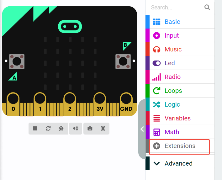
Open the offline programming software MakeCode and enter the programming interface. Click [New] and add the Yahboom software package https://github.com/YahboomTechnology/SuperBitLibV2 to start programming.
3.1 Adding extension packages
3.2 Building blocks used
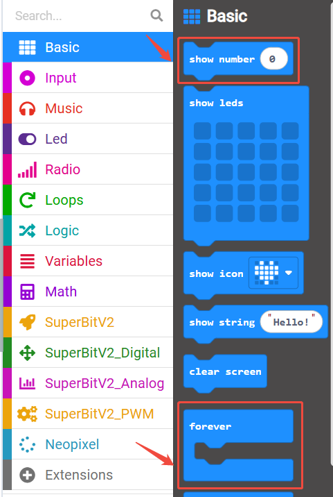
The locations of the building blocks required for this programming are shown in the figure below.

3.3 Combination building blocks
The summary procedure is shown in the figure below.
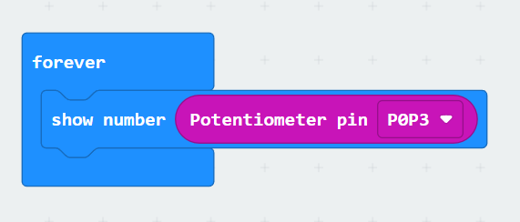
You can also directly open the Adjust-potentiometer.hex file provided in this experiment and drag it into the browser that opens the URL, and the program diagram of this project source code will be automatically opened.
4.Experimental phenomenon
After the program runs successfully, twist the potentiometer and the microbit dot matrix will display the current resistance value of the potentiometer.