ROS Control
1. Functional Description
This function enables control of the robot's speed, buzzer, and servos through ROS2 topic tools. It also enables access to low-level data, such as radar data, IMU data, and version information.
2. Preparation
2.1. Pre-use Instructions
This lesson uses the Raspberry Pi as an example. For Raspberry Pi and Jetson-Nano boards, you need to open a terminal on the host computer and enter the command to enter the Docker container. Once inside the Docker container, enter the commands mentioned in this lesson in the terminal. For instructions on entering the Docker container from the host computer, refer to [01. Robot Configuration and Operation Guide] -- [5.Enter Docker (For JETSON Nano and RPi 5)]. For Orin boards, simply open a terminal and enter the commands mentioned in this lesson.
2.2 Pre-use Configuration
This vehicle is equipped with a USB camera, a depth camera, and two different LiDAR models. However, since the device cannot be automatically recognized, the machine type and LiDAR model must be manually configured.
For the Raspberry Pi 5 controller, you must first enter the Docker container. This is not necessary for the Orin .
Change the LiDAR and camera types according to the vehicle model as follows.
xxxxxxxxxxroot@ubuntu:/# cdroot@ubuntu:~# vim .bashrc
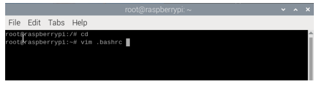
Find this location and press i on your keyboard to change the camera and LiDAR models to the corresponding ones. The default values are Tmini and Nuwa.
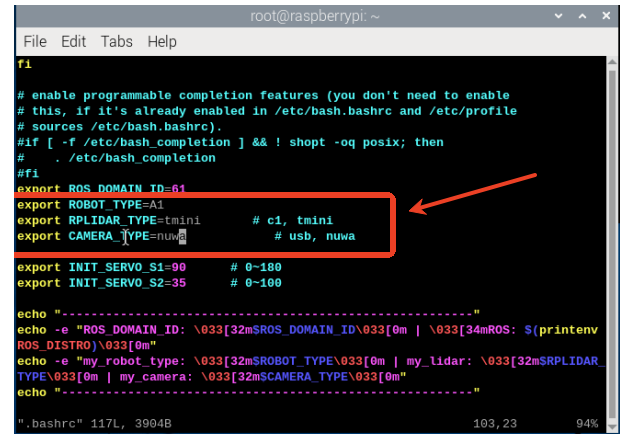
After completing the modification, save and exit vim, then execute:
xxxxxxxxxxroot@raspberrypi:~# source .bashrc--------------------------------------------------------ROS_DOMAIN_ID: 61 | ROS: humblemy_robot_type: A1 | my_lidar: tmini | my_camera: nuwa--------------------------------------------------------root@raspberrypi:~#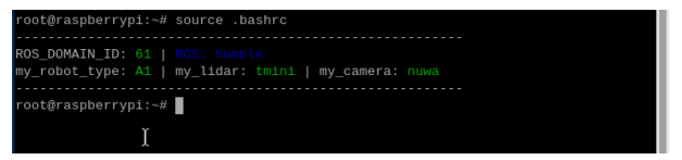
3. Program Startup
3.1. Startup Command
For the Raspberry Pi 5 controller, you must first enter the Docker container. For the Orin controller, this is not necessary.
Enter the Docker container (for steps, see [Docker Course] --- [4. Docker Startup Script]).
All the following commands must be executed from the Docker terminal within the same Docker container.(For steps, see [Docker Course] --- [3. Docker Submission and Multi-Terminal Access]).
To start chassis data, enter the following command in the terminal:
xxxxxxxxxxros2 run yahboomcar_bringup Ackman_driver_A1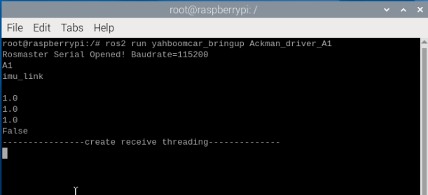
You can view the current node name by entering the following command:
xxxxxxxxxxros2 node list

Enter the following command in the terminal to view the available topics.
xxxxxxxxxxros2 topic list
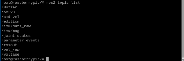
| Topic Name | Topic Content |
|---|---|
| /Buzzer | Buzzer |
| /Servo | Servo s1, s2 |
| /cmd_vel | Speed Control |
| /edition | Version Information |
| /imu/data_raw | IMU Sensor Data |
| /imu/mag | IMU Magnetometer Data |
| /vel_raw | Vehicle Speed Information |
| /voltage | Battery voltage information |
Then enter the following command to query the topic message data types of the topics published/subscribed by this node.
xxxxxxxxxxros2 node info /driver_node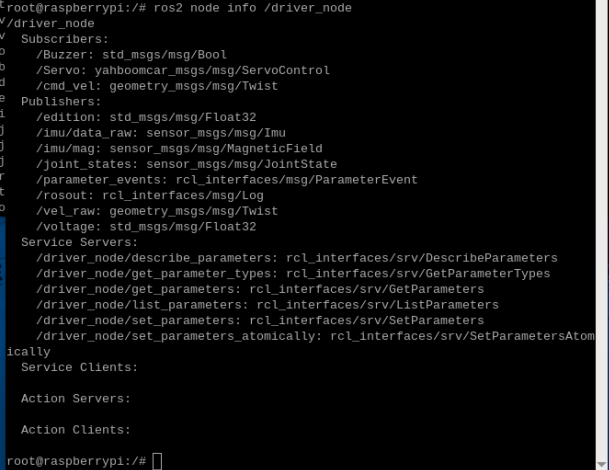
3.2. Publishing Control Commands
Based on the table of subscribed topics, use the following command format: ros2 topic pub topic name topic message data type message data --once to publish a frame of control data.
- Issue Speed Control Commands
For the first test, it's recommended to set up the car and test it without its wheels touching the ground. We'll set the car to move forward at a linear velocity of 0.1 m/s. Enter the following command in the terminal:
xxxxxxxxxxros2 topic pub /cmd_vel geometry_msgs/msg/Twist "{linear: {x: 0.1, y: 0.0, z: 0.0}, angular: {x: 0.0, y: 0.0, z: 0.0}}" --onceAfter running, the car will move forward at a speed of 0.1 m/s. Similarly, to control the car to move at an angle of 1.0 rad/s, assign the z value of angular_r to the value of angular_r (note that turning requires not only the angular velocity but also the linear velocity, as Ackerman chassis turning requires forward velocity).** The command is as follows:
xxxxxxxxxxros2 topic pub /cmd_vel geometry_msgs/msg/Twist "{linear: {x: 0.1, y: 0.0, z: 0.0}, angular: {x: 0.0, y: 0.0, z: 1.0}}" --onceAfter running, the robot will rotate. To stop the robot, simply publish both the linear velocity and angular velocity to 0. When the velocity reaches 0, the front wheel servo automatically corrects. The command is as follows:
xxxxxxxxxxros2 topic pub /cmd_vel geometry_msgs/msg/Twist "{linear: {x: 0.0, y: 0.0, z: 0.0}, angular: {x: 0.0, y: 0.0, z: 0.0}}" --onceThe "--once" flag indicates that only one frame of message data will be sent. For other parameters of pub, refer to [19. Common ROS2 Command Tools] in [15. ROS2 Basics Course] of this product course.
3.3. Controlling the Buzzer
To turn on the buzzer, enter the following command in the terminal:
xxxxxxxxxxros2 topic pub /Buzzer std_msgs/msg/Bool "data: 1" --once
To turn off the buzzer, enter the following command in the terminal:
xxxxxxxxxxros2 topic pub /Buzzer std_msgs/msg/Bool "data: 0" --once
3.4. Controlling the Servo
Note: This command is only required if you purchased the gimbal USB camera version; it is not required for the depth camera version
To control the servo, enter the following command in the terminal:
xxxxxxxxxxros2 topic pub -1 /Servo yahboomcar_msgs/msg/ServoControl "{'s1': 90, 's2': 35}"

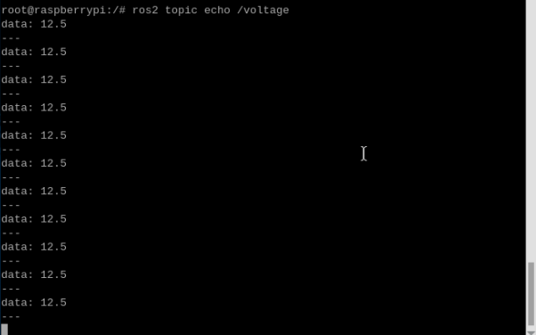
3.5. Reading Battery Voltage
Terminal Input:
xxxxxxxxxxros2 topic echo /voltage
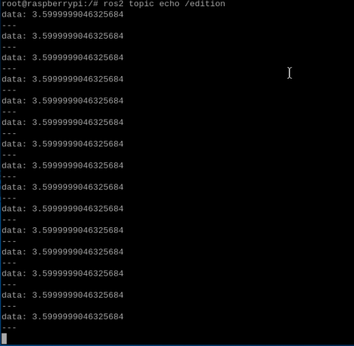
3.6. Reading Firmware Version
Terminal Input:
xxxxxxxxxxros2 topic echo /edition
4. Program Core Source Code Analysis
Using Ackman_driver_A1.py as an example,
xxxxxxxxxxfrom Rosmaster_Lib import Rosmaster #Import the driver libraryself.car = Rosmaster() #Instantiate the Rosmaster object#create subscriberself.sub_cmd_vel = self.create_subscription(Twist,"cmd_vel",self.cmd_vel_callback,1)self.sub_BUzzer = self.create_subscription(Bool,"Buzzer",self.Buzzercallback,100)#create publisherself.EdiPublisher = self.create_publisher(Float32,"edition",100)self.volPublisher = self.create_publisher(Float32,"voltage",100)self.staPublisher = self.create_publisher(JointState,"joint_states",100)self.velPublisher = self.create_publisher(Twist,"vel_raw",50)self.imuPublisher = self.create_publisher(Imu,"/imu/data_raw",100)self.magPublisher = self.create_publisher(MagneticField,"/imu/mag",100)#Call the library and read the information of the ros expansion boardedition.data = self.car.get_version()*1.0battery.data = self.car.get_battery_voltage()*1.0ax, ay, az = self.car.get_accelerometer_data()gx, gy, gz = self.car.get_gyroscope_data()mx, my, mz = self.car.get_magnetometer_data()vx, vy, angular = self.car.get_motion_data()#Publish topic dataself.imuPublisher.publish(imu)self.magPublisher.publish(mag)self.volPublisher.publish(battery)self.EdiPublisher.publish(edition)self.velPublisher.publish(twist)#Subscriber callback functiondef cmd_vel_callback(self, msg)def Buzzercallback(self, msg):