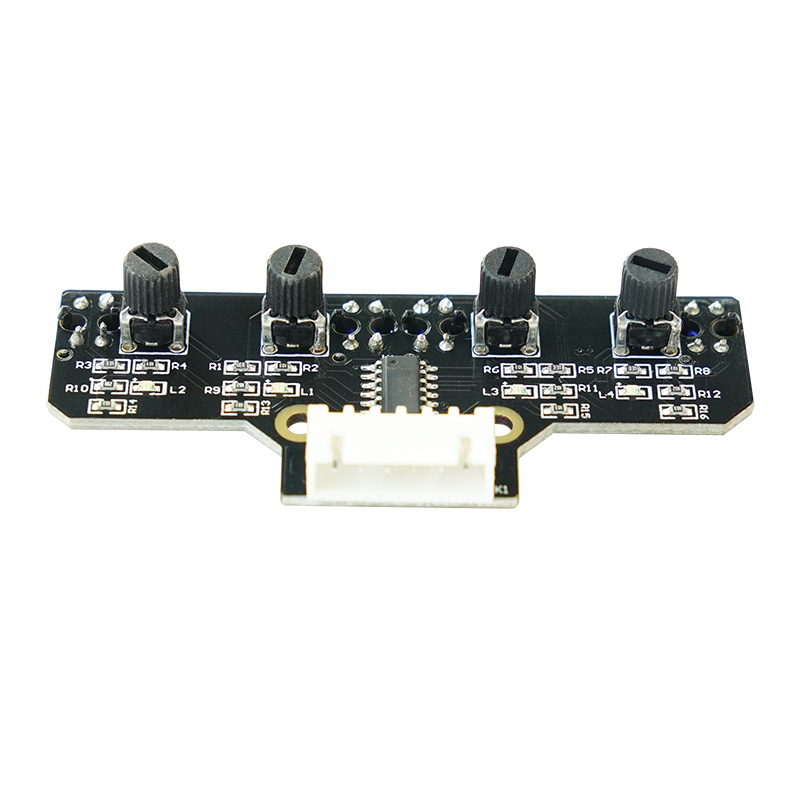
Welcome to 4-channel Tracking Module repository
4 channel tracking module
1. Description of Pin
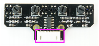
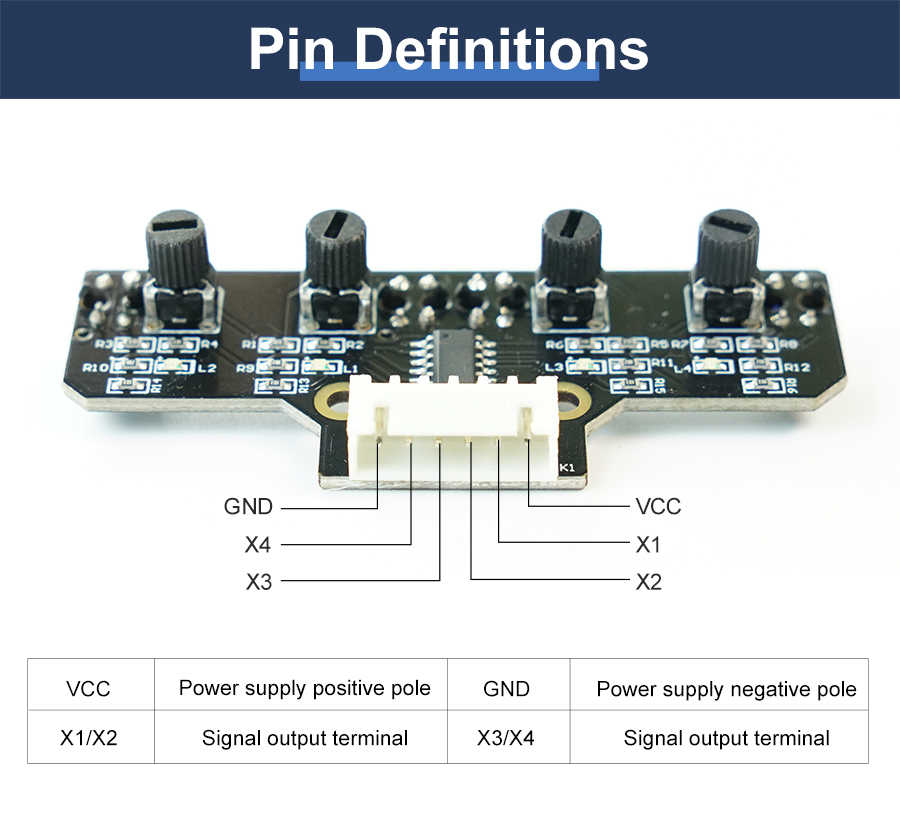
1-1 Position of Pins
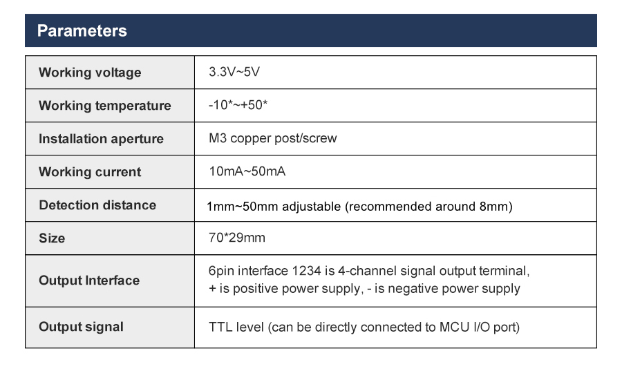
The anti-reverse socket is used in here, and it can be connected by cable or DuPont line.
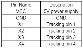
2. Infrared tube
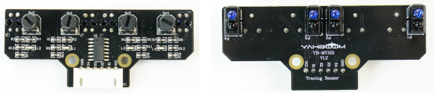
This infrared line module has four pairs of infrared pair tubes.
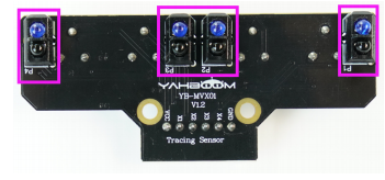
2-1 Position of infrared tube
The basic principle of the infrared tracking sensor is to take advantage of the reflective nature of the object. In this experiment, we need the effect that the robot car walk along the black line. When the infrared light is emitted onto the black line, it will be absorbed by the black line, but when the infrared light is emitted onto the other colors line, it will be reflected onto the infrared receiver pin.
3.Infrared indicator light
There are four infrared indicators on this module.
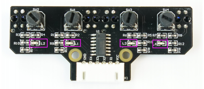
3-1 Position of infrared indicator light
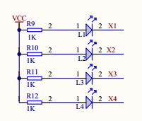
3-2 Schematic
3-1)When the black line is detected, the corresponding indicator of the tracking module is on, and the port level is LOW.
3-2)When the black line is not detected, the corresponding indicator of the tracking module is off, and the port level is HIGH.
4.Adjustable resistor
This module has four adjustable resistances.
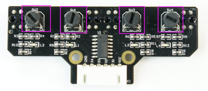
4-1 Position of adjustable resistor
In the tracking experiment, it is necessary to adjust the potentiometer of the infrared tracking module to optimize the sensitivity of the tracking.
The debugging method is as follows:
4-1)Adjusting the adjustable resistor [SW1] so that when the photoelectric sensor [P1] is facing the white bottom surface, the LED light [L1] is off, and when facing the bottom of the black line, the LED light [L1] is on.
4-2)Adjusting the adjustable resistor [SW2] so that when the photoelectric sensor [P2] is facing the white bottom surface, the LED light [L2] is off, and when facing the bottom of the black line, the LED light [L2] is on.
4-3)Adjusting the adjustable resistor [SW3] so that when the photoelectric sensor [P3] is facing the white bottom surface, the LED light [L3] is off, and when facing the bottom of the black line, the LED light [L3] is on.
4-4)Adjusting the adjustable resistor [SW4] so that when the photoelectric sensor [P4] is facing the white bottom surface, the LED light [L4] is off, and when facing the bottom of the black line, the LED light [L4] is on.
5.MCU
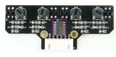
5-1 Position of MCU
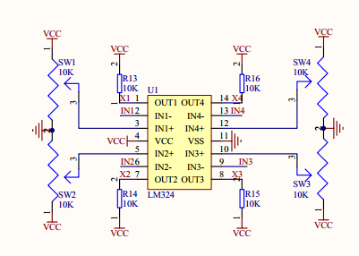
5-2 Schematic
This is master chip of module.
Hardware connection: (The definition of the pin can be changed in the program by yourself)
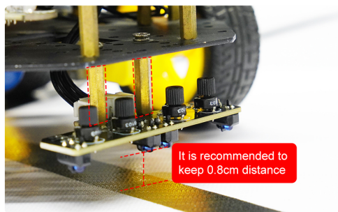
This module is suitable for some robots and smart car. We will provide Arduino, Raspberry driver source code.
! ! ! Note
In order to avoid the influence of sunlight on infrared light, the experiment needs to be carried out in an indoor environment without strong light.